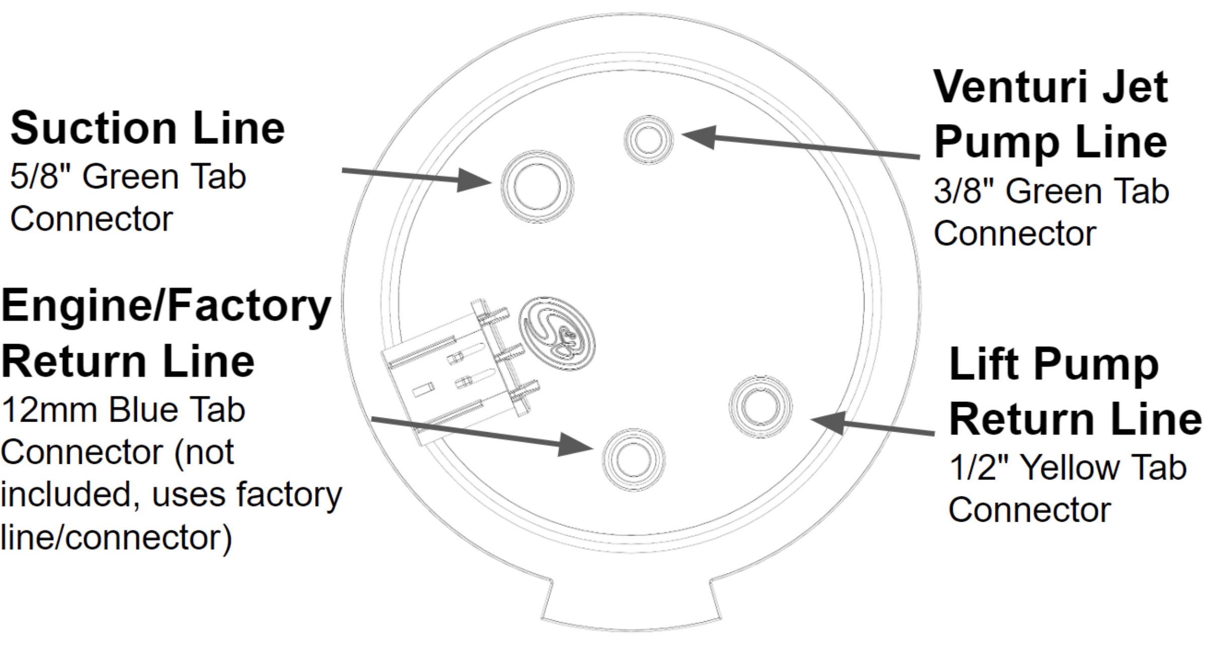
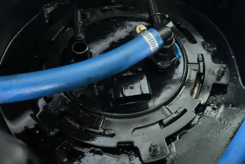
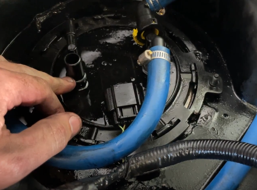
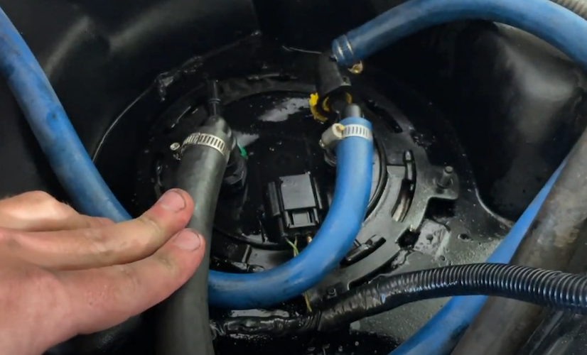
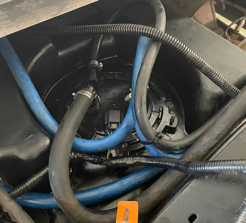
Connect the factory return (elbow quick connect fitting with a blue tab) to the location shown in the diagram.
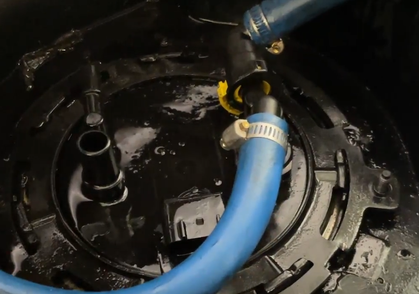
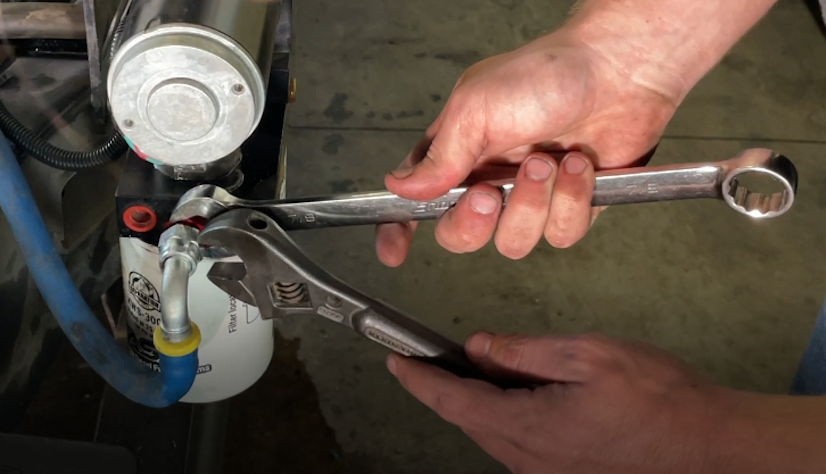
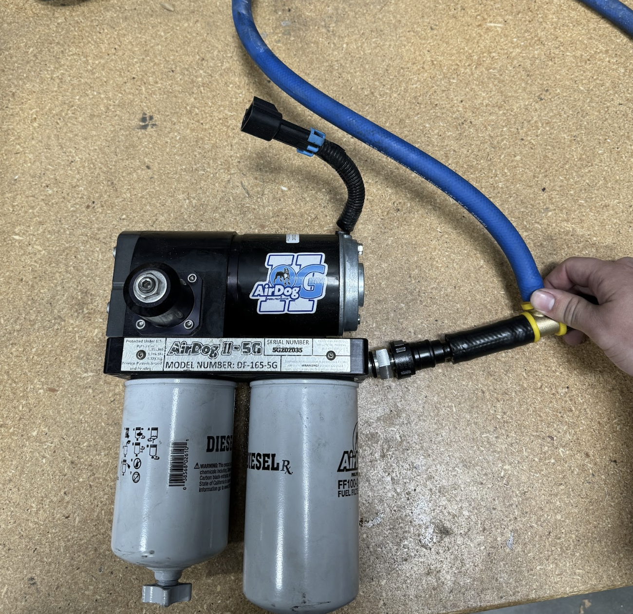
For FASS pumps, you will use the supplied quick connect to quick connect adapter (FASS Part number DB-4646) in the location of the factory lift pump according to FASS instructions step 4.
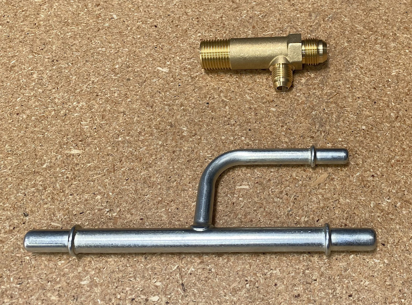
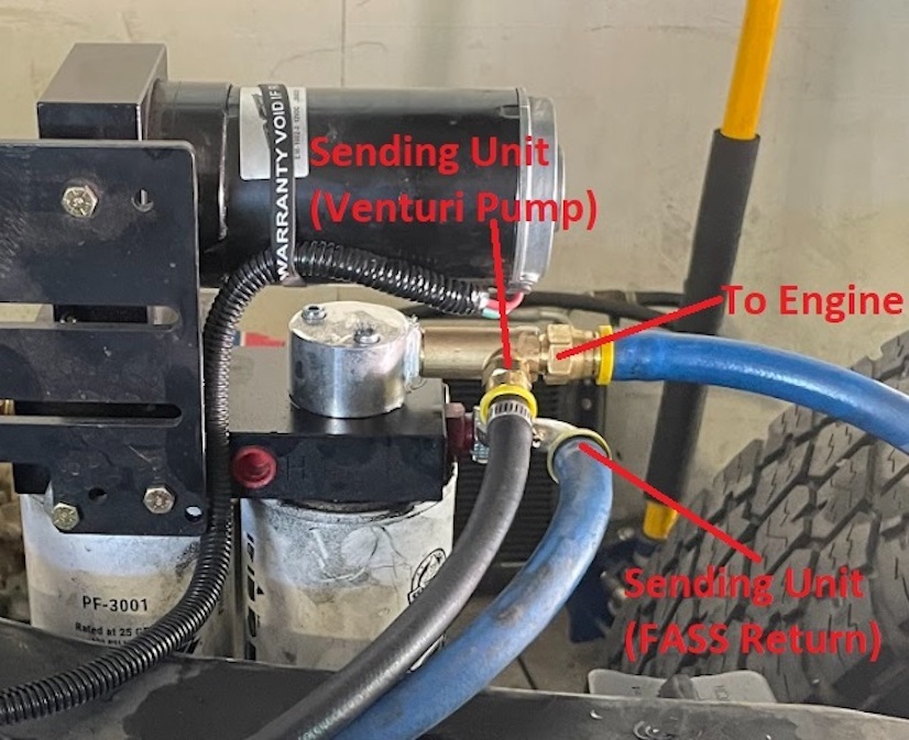
For AirDog lift pumps, you will connect their supplied Return Tee (AirDog part number 001-4B-1-0067) where the factory lift pump used according to AirDog instruction step 9-1. However, unlike the AirDog instructions step 9-2 and 9-3, you will cap the small end of the Tee. This is different because the S&B Sending Unit will have the AirDog return routed directly to the sending unit instead of merging the factory return and AirDog return into one line.