HCT Disassembly
If you have a HCT model, use a torx to remove the engine cover.
Note: This intake kit may not fit with the following Aftermarket Parts installed:
- Body Lift or Lowering Kit
- Custom Hood
- Throttle Body Spacer / Upgrade
Please read the entire product guide before proceeding.
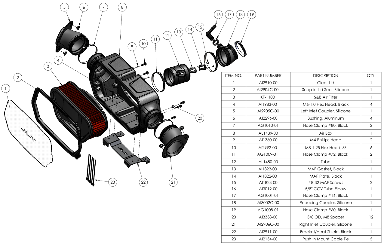
- Ensure all parts are present.
- If you are missing any of the components, call our customer support at (909) 947-0015.
- Do not work on your vehicle while the engine is hot.
- Make sure the engine is turned off and the vehicle is in Park or the Parking Brake is set.
- 5/16 or 8mm socket/nut driver
- Flat head screw driver
-X-Acto knife
- Phillips Head screw driver
If you have a HCT model, use a torx to remove the engine cover.
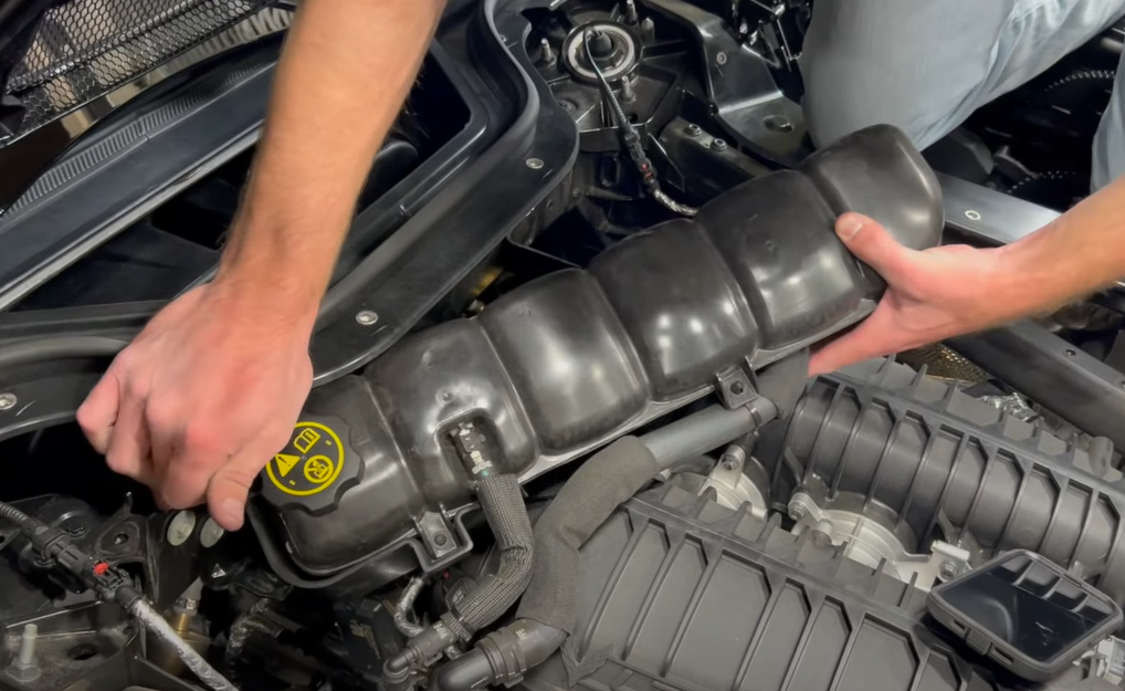
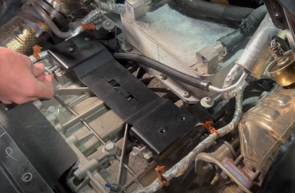
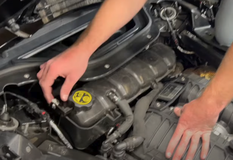
Use a 10mm socket to to the coolant tank out of the way/ This will give you more room to work
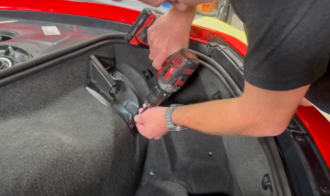
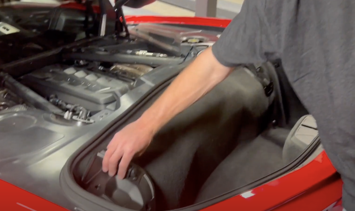
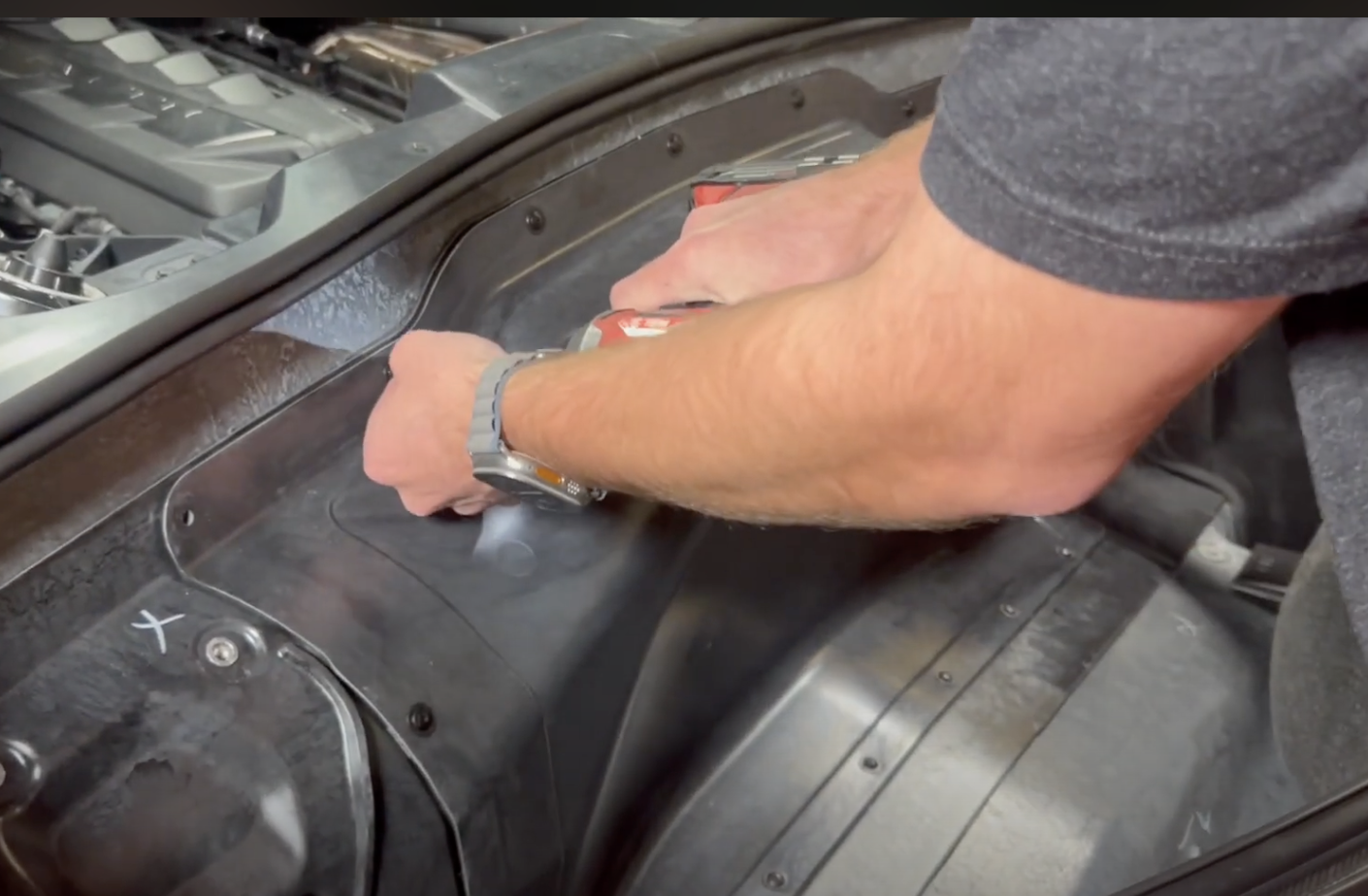
Remove the 8 bolts that hold the driver and passenger side brackets in the trunk. Also remove the hand fasteners below the brackets
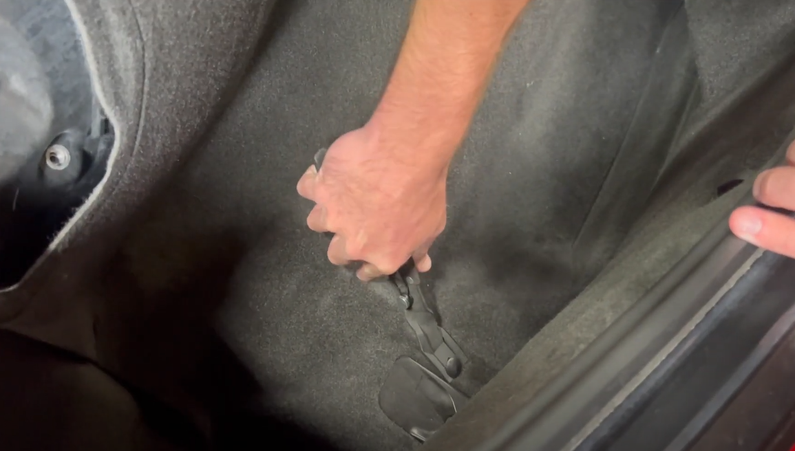
Remove the lower push rivets from the carpet.
Remove the carpet from the vehicle.
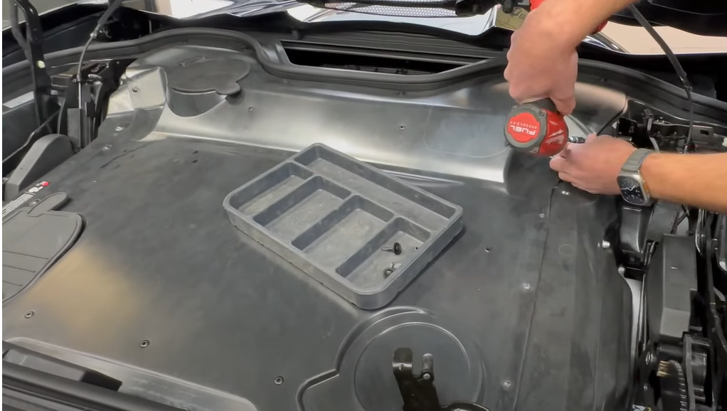
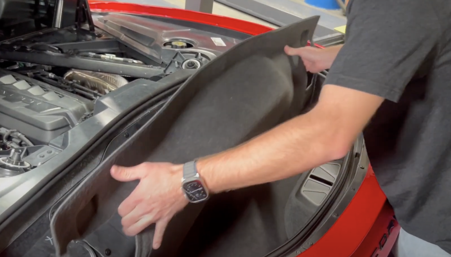
Now remove the bolts that hold down the trunk cover.
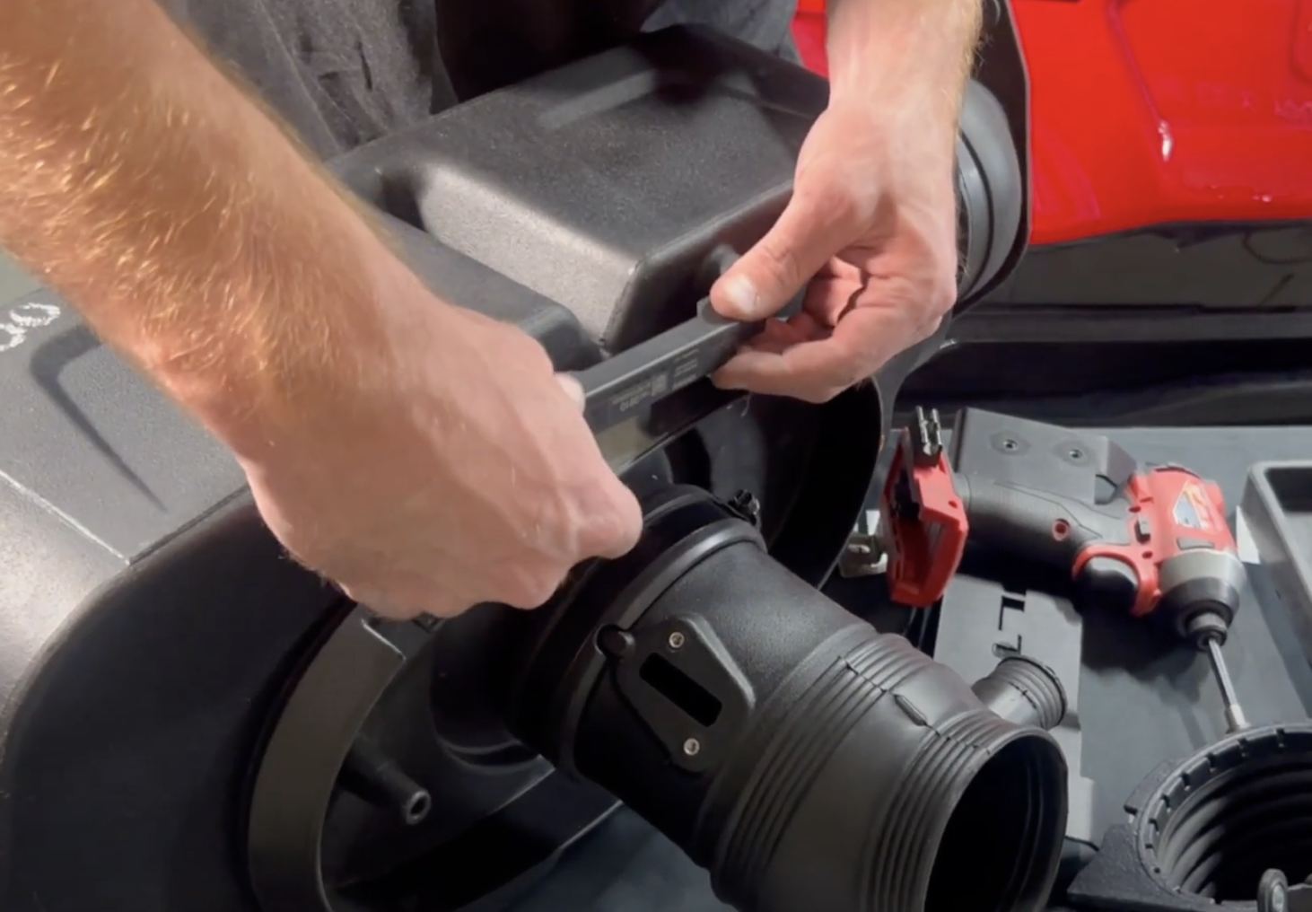
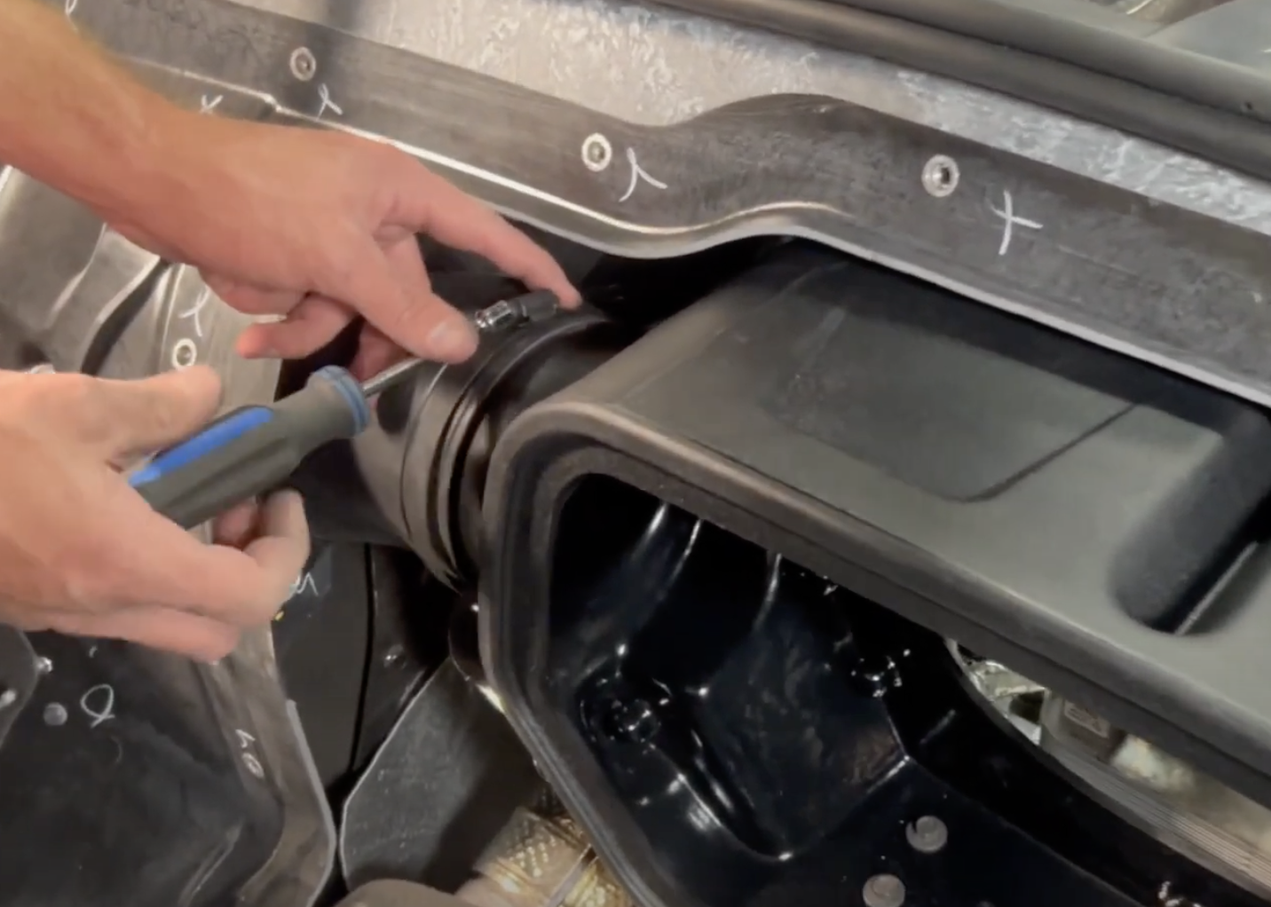
Remove the 8 bolts that hold the side inlets to the intake box. Remove both side inlets
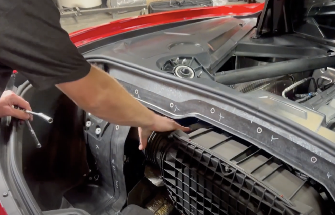
Remove the two airbox mounting bolts.
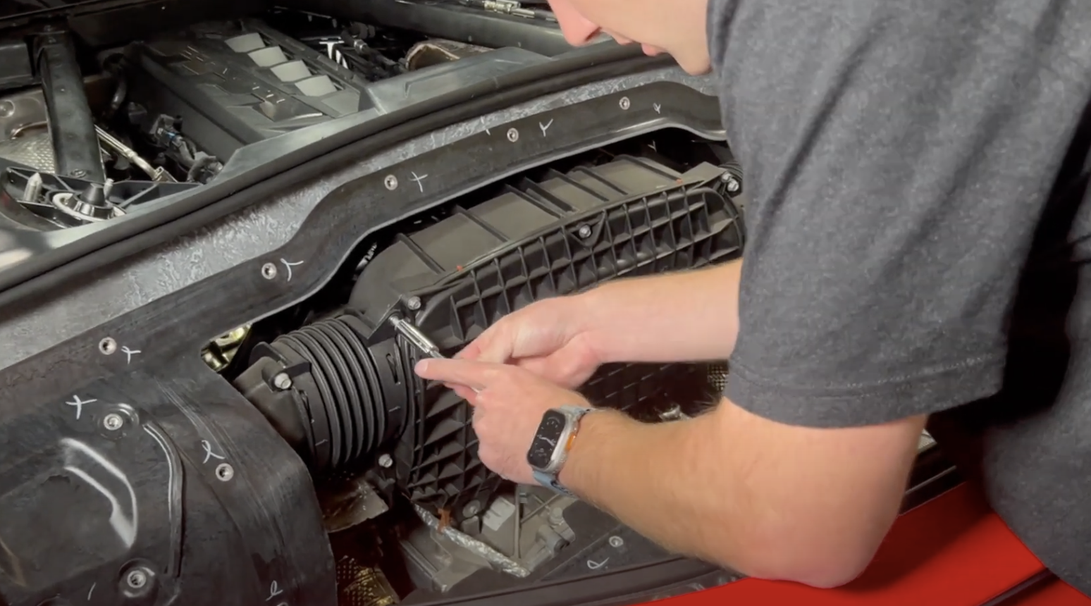
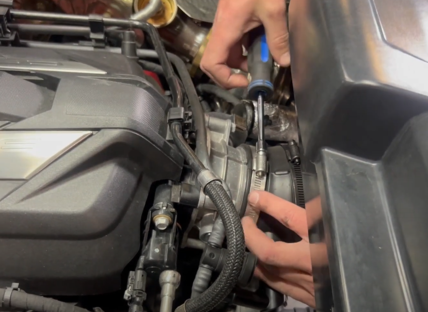
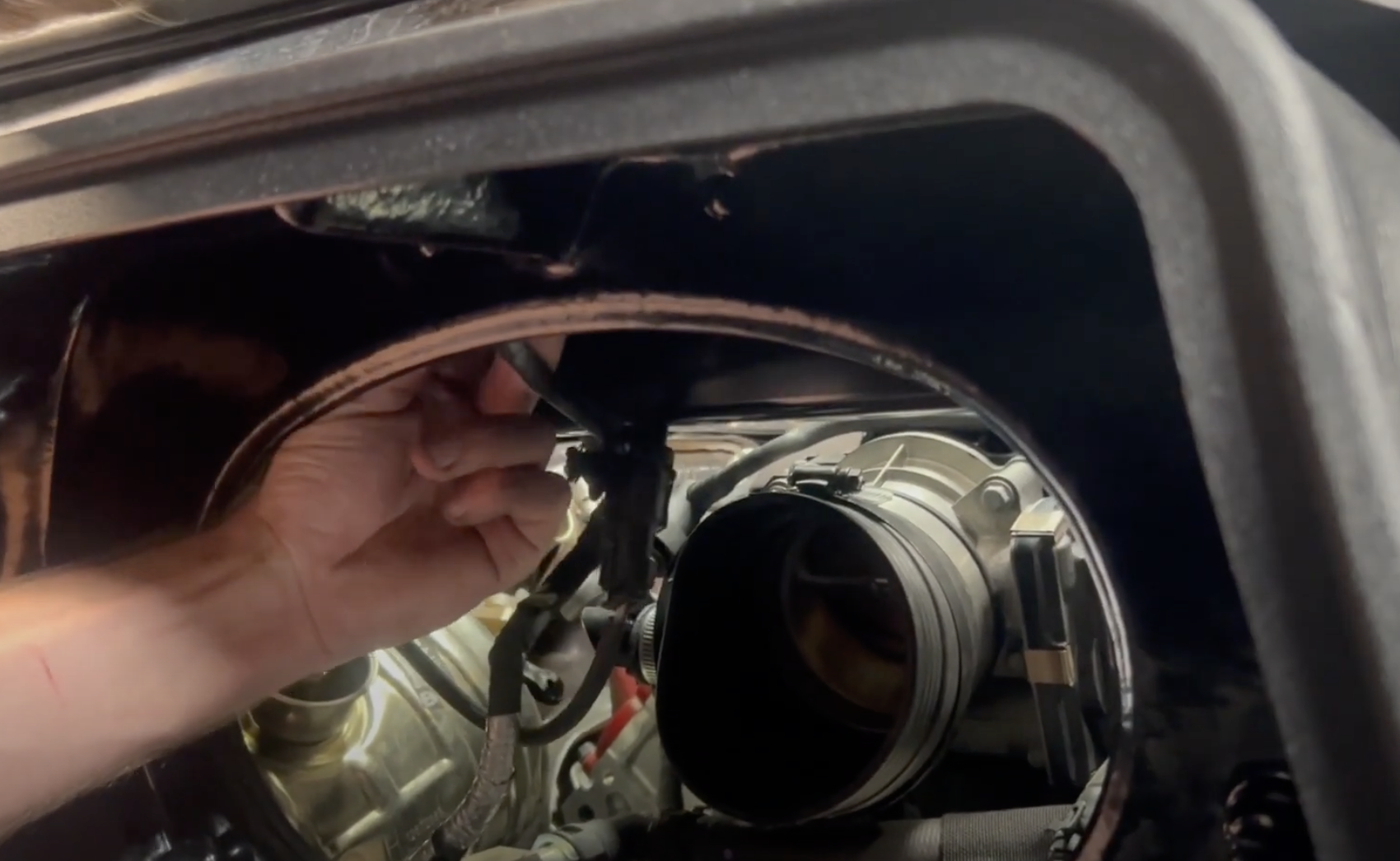
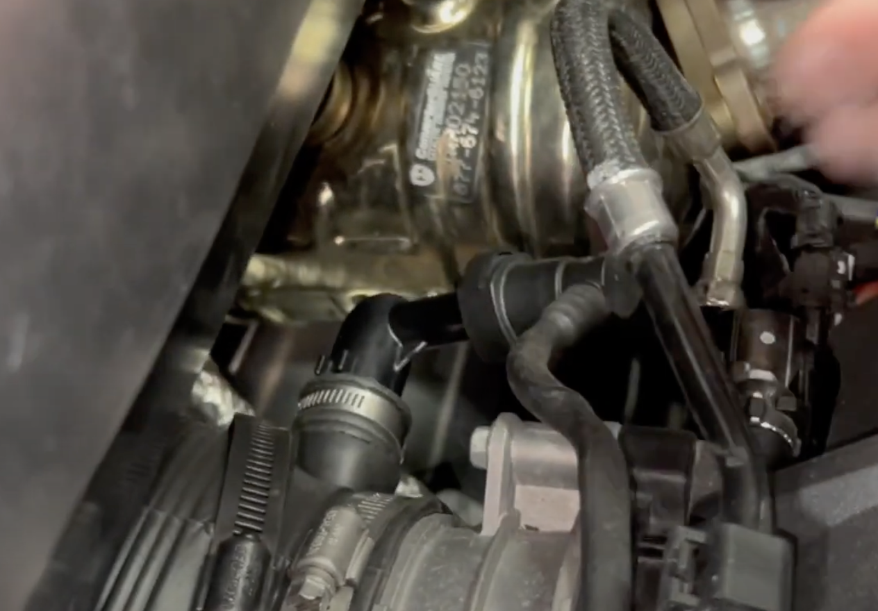
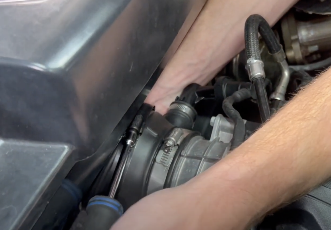
Loosen the hose clamp on the throttle body side. Then remove the PCV quick connect next to the throttle body (depress the black tab).
Remove the MAF sensor on top of the intake tube. You will need to slide out the white locking tab and depress the button on the sensor.
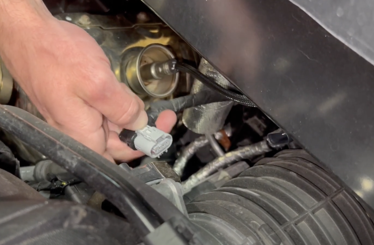
Remove the O2 sensors by unclipping each one with a panel popper.
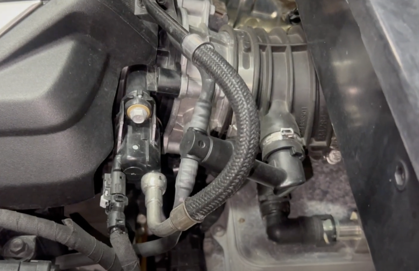
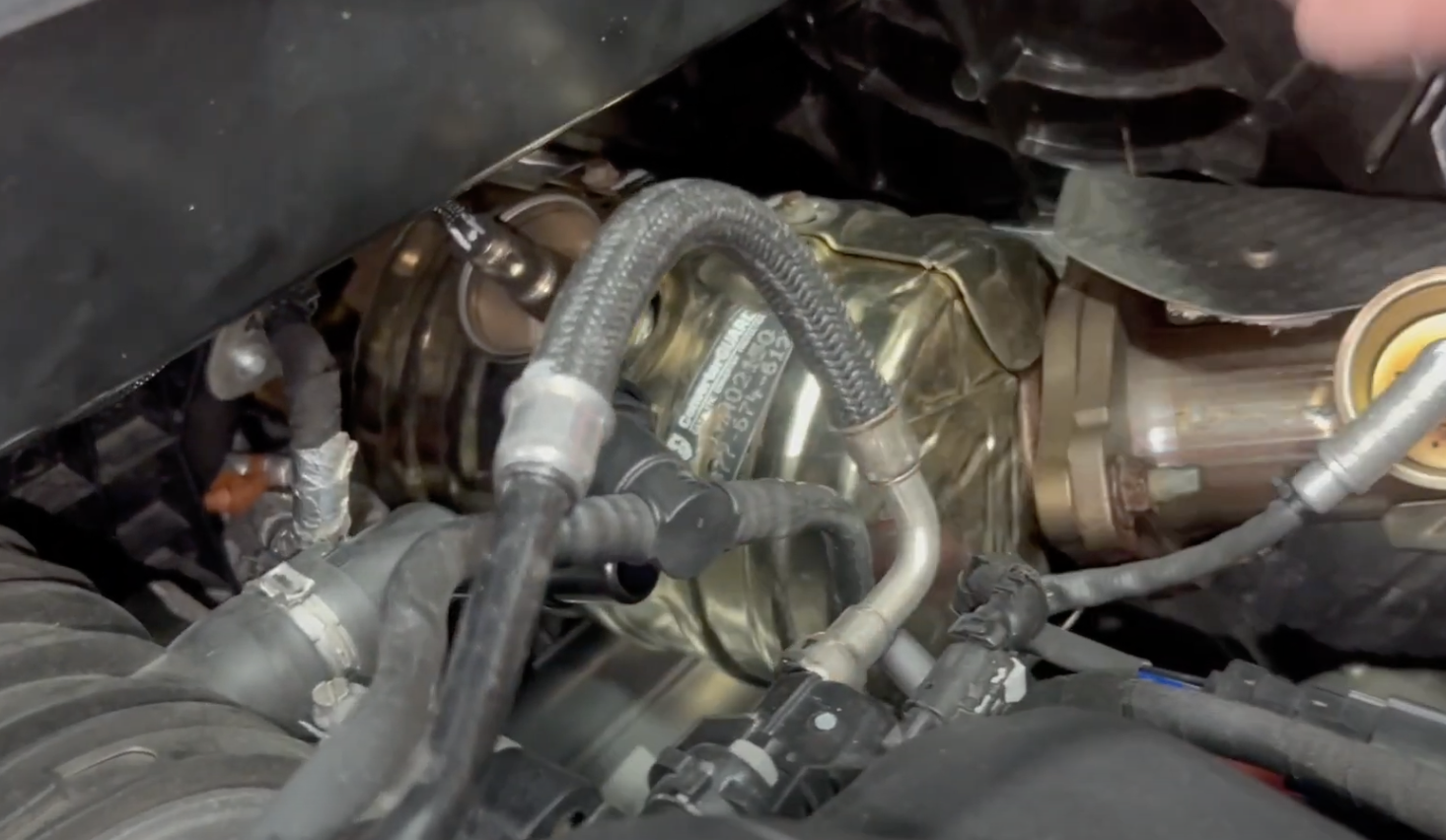
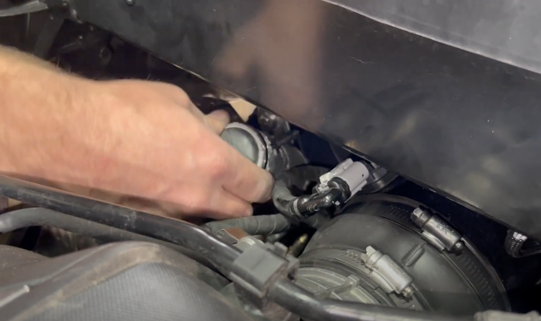
Remove the canister that is seen in the picture.
Now repeat the same process on the driver's side and remove the O2 sensors.
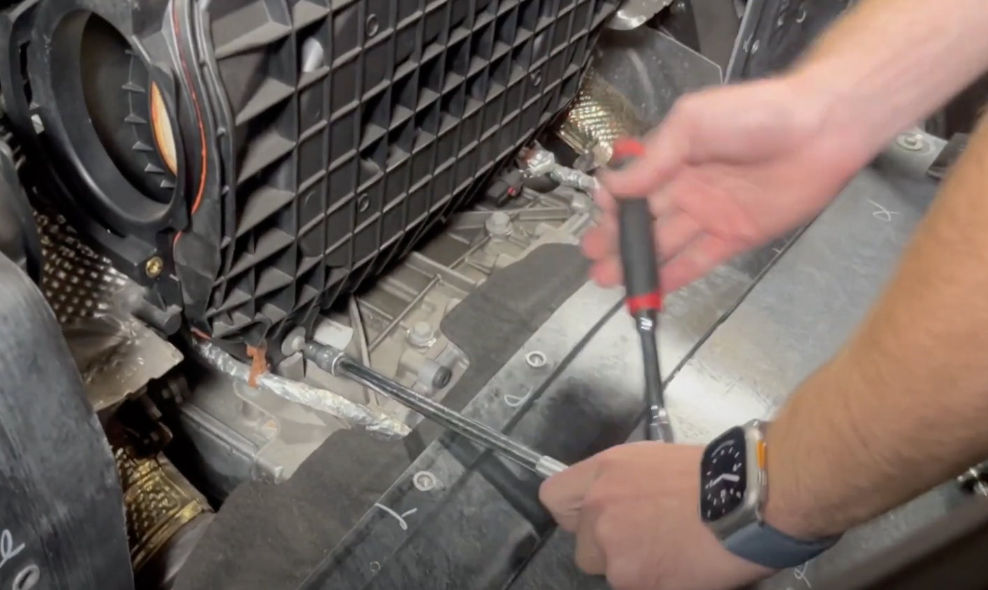
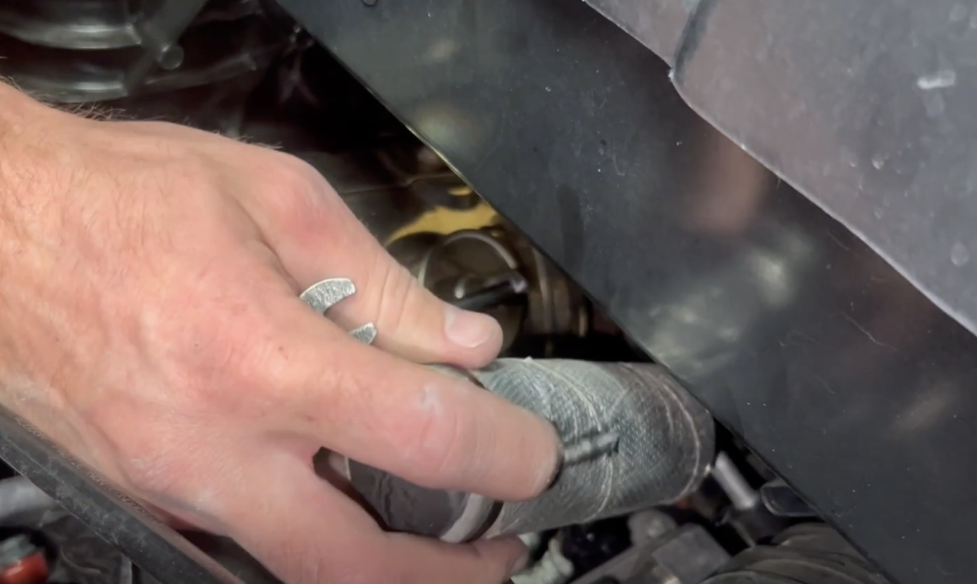
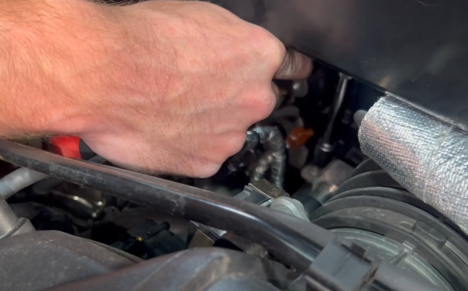
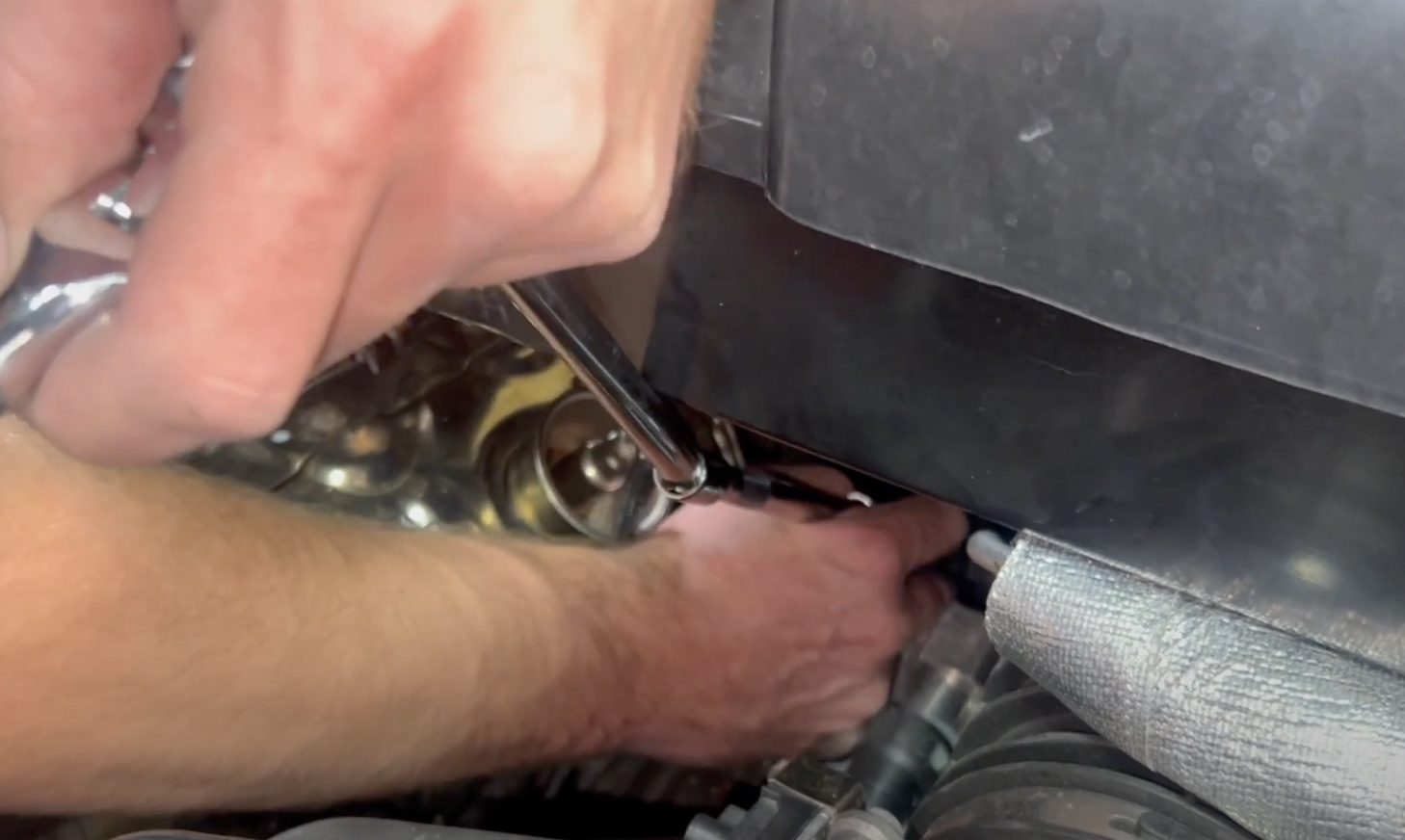
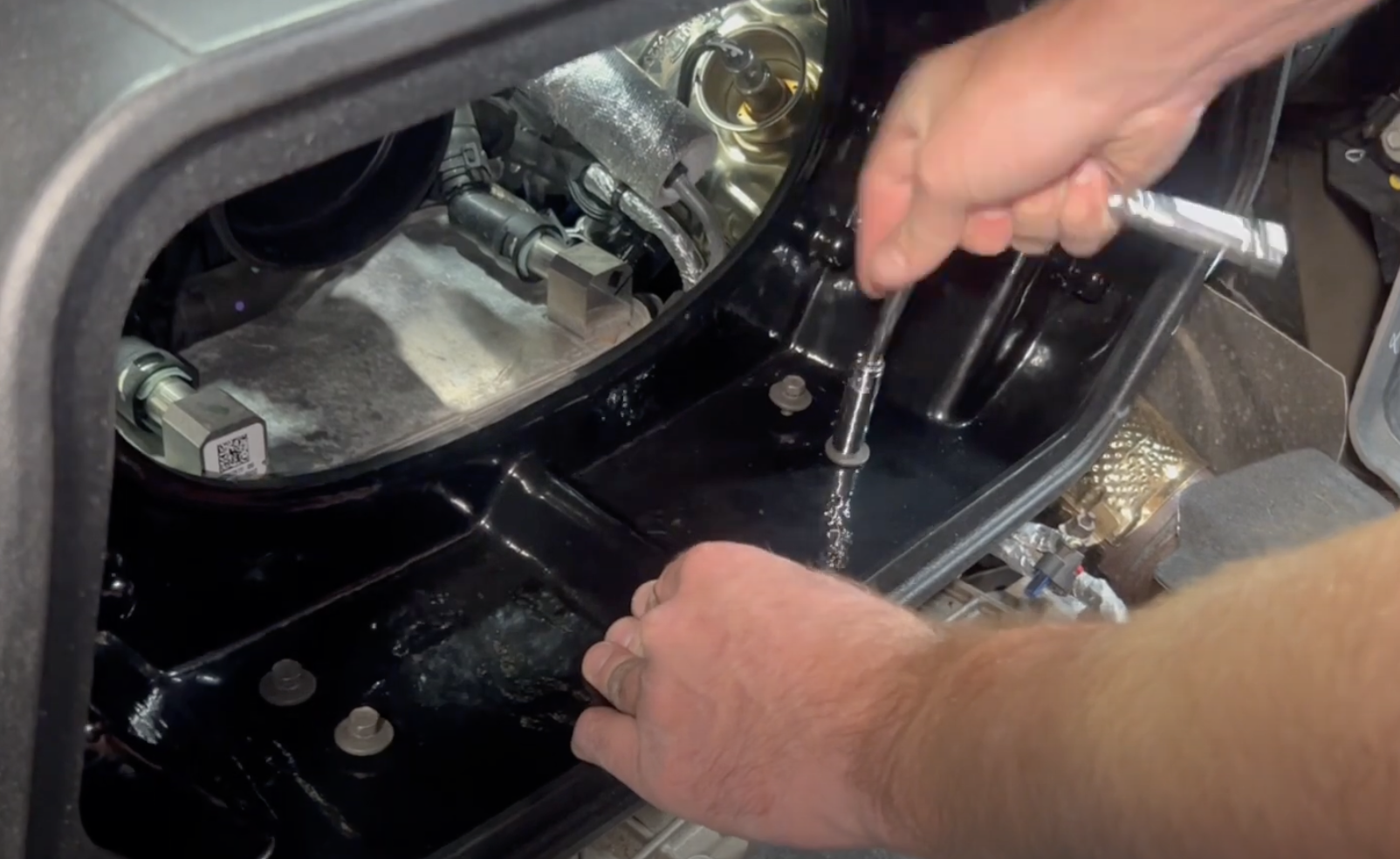
Remove the bolts that are at the base of the airbox on each side with a long extension and wobble. You can also remove it with a shorter extension if your extension and ratchet fits under the support bar.
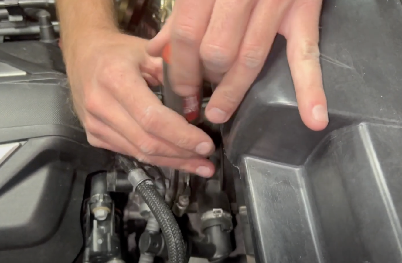
Now take a magnet or claw tool and remove the bolt.
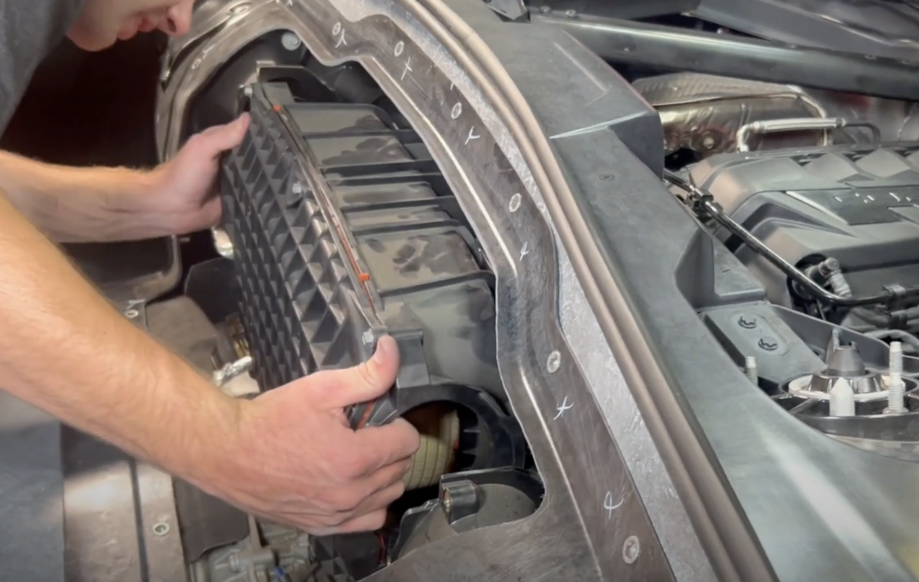
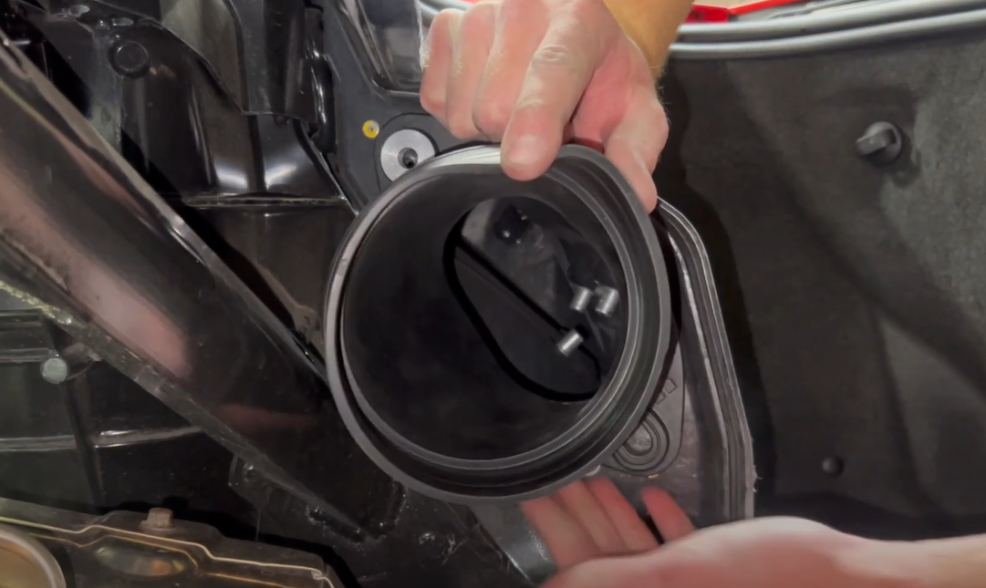
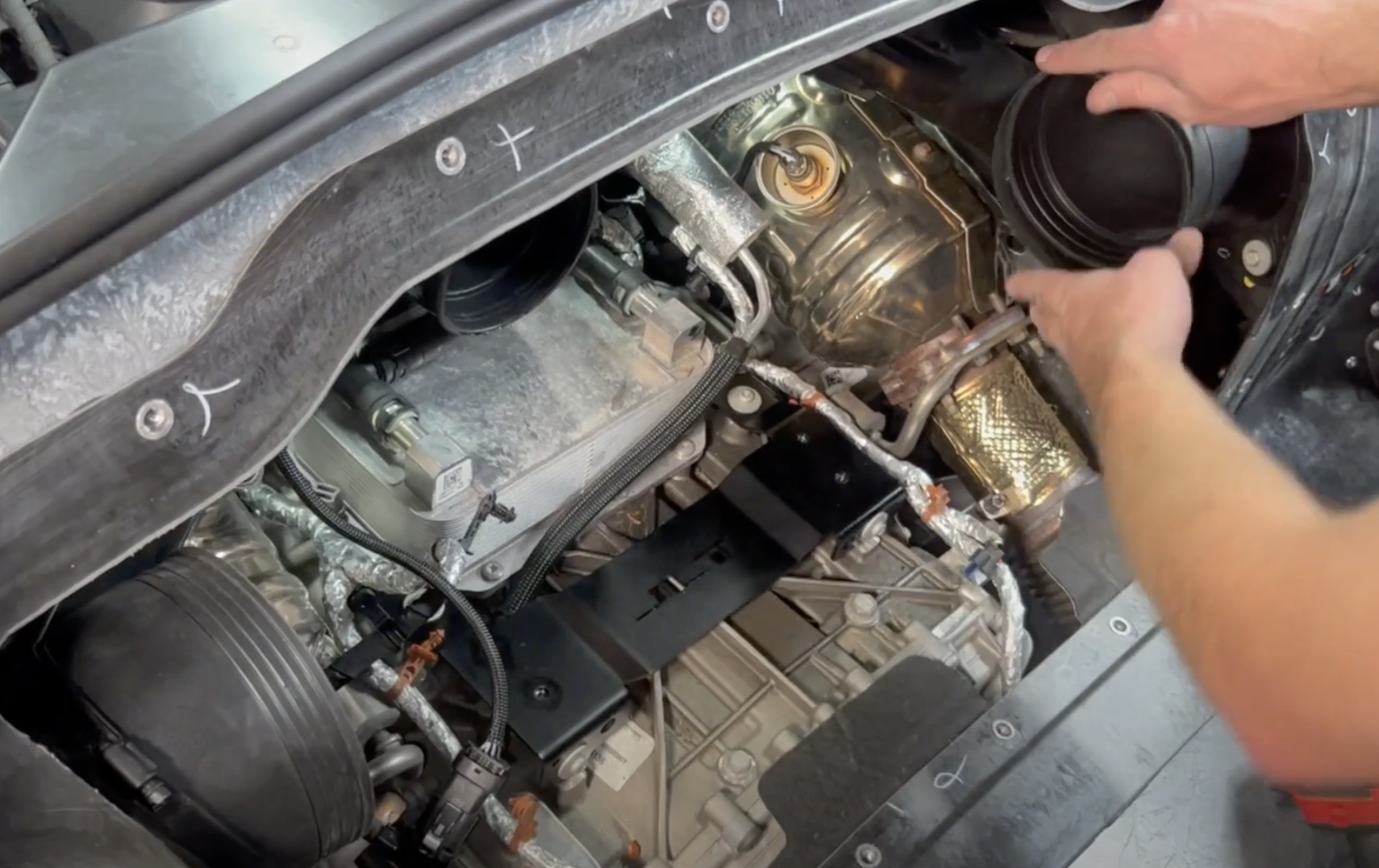
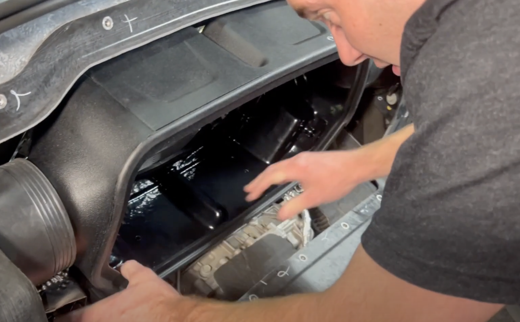
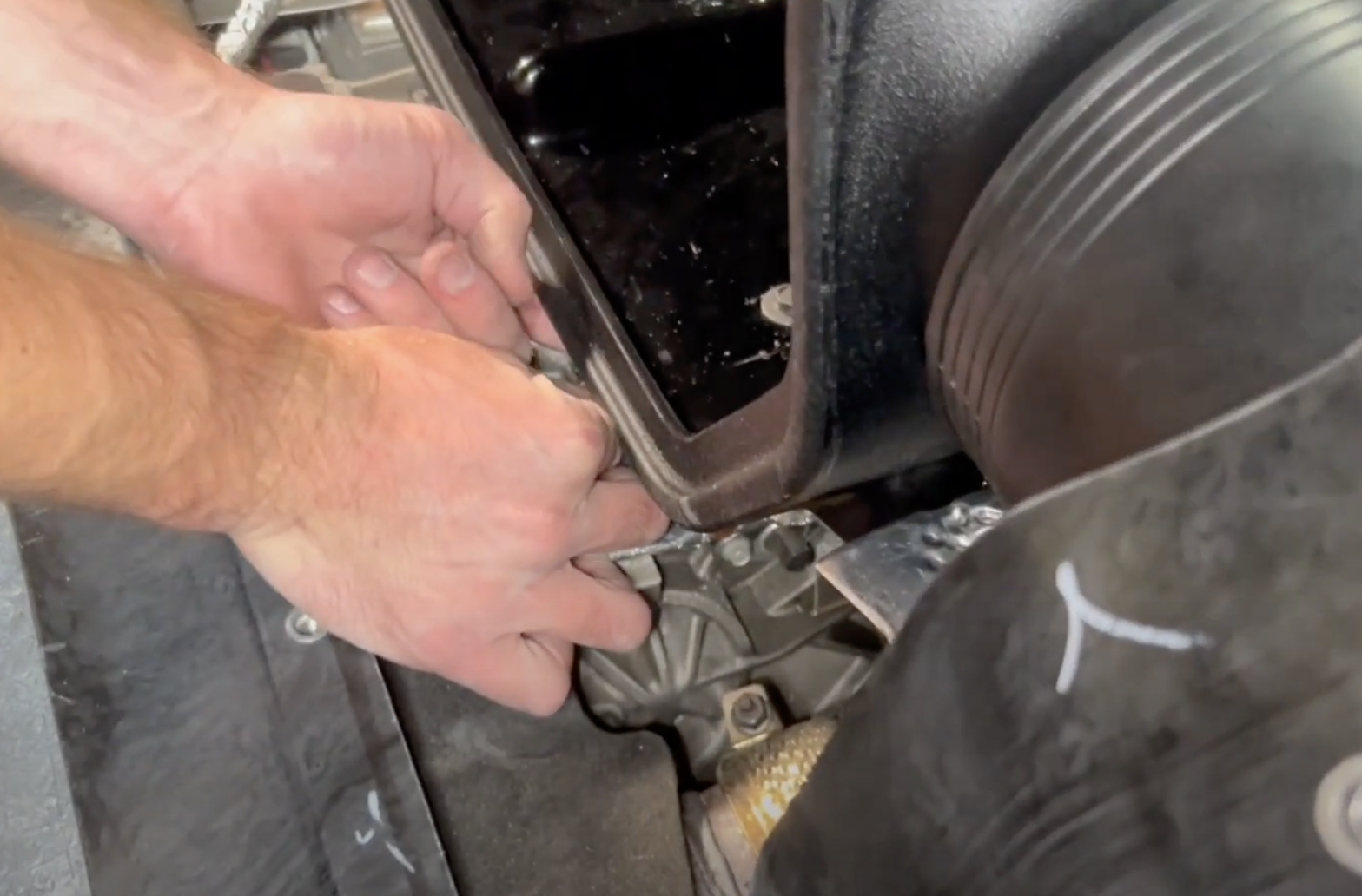
Remove the stock airbox.
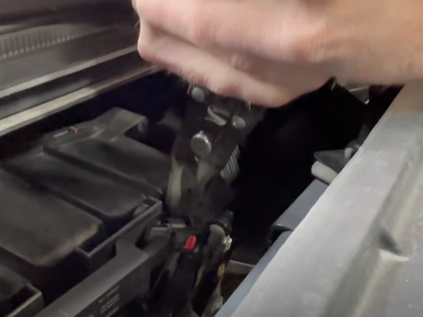
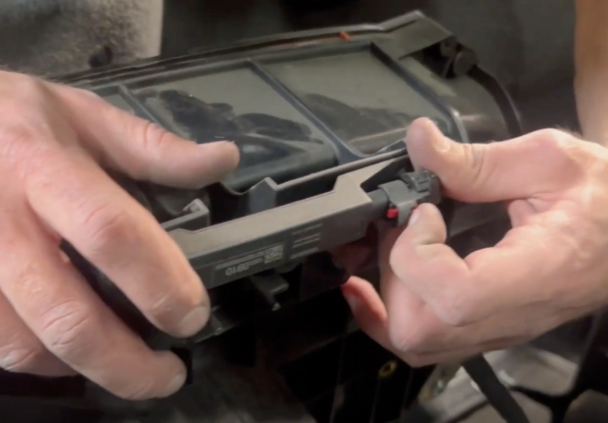
Remove the GPS antenna connector by sliding the red lock out and depressing the button.
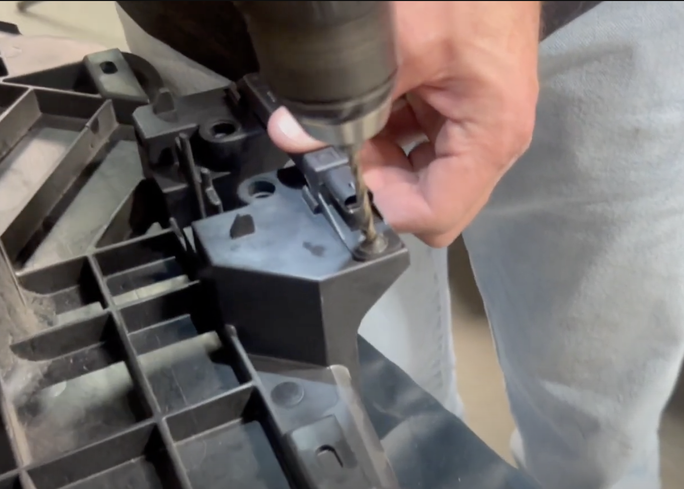
Drill out both heat stakes. Then transfer the GPS to the S&B intake and secure it down with the included bolts
Transfer the heat shields to the JLT airbox. If the heat shield do not have "spacers" built into the area where the bolts go through, use the included S&B 1/4" thick spacers
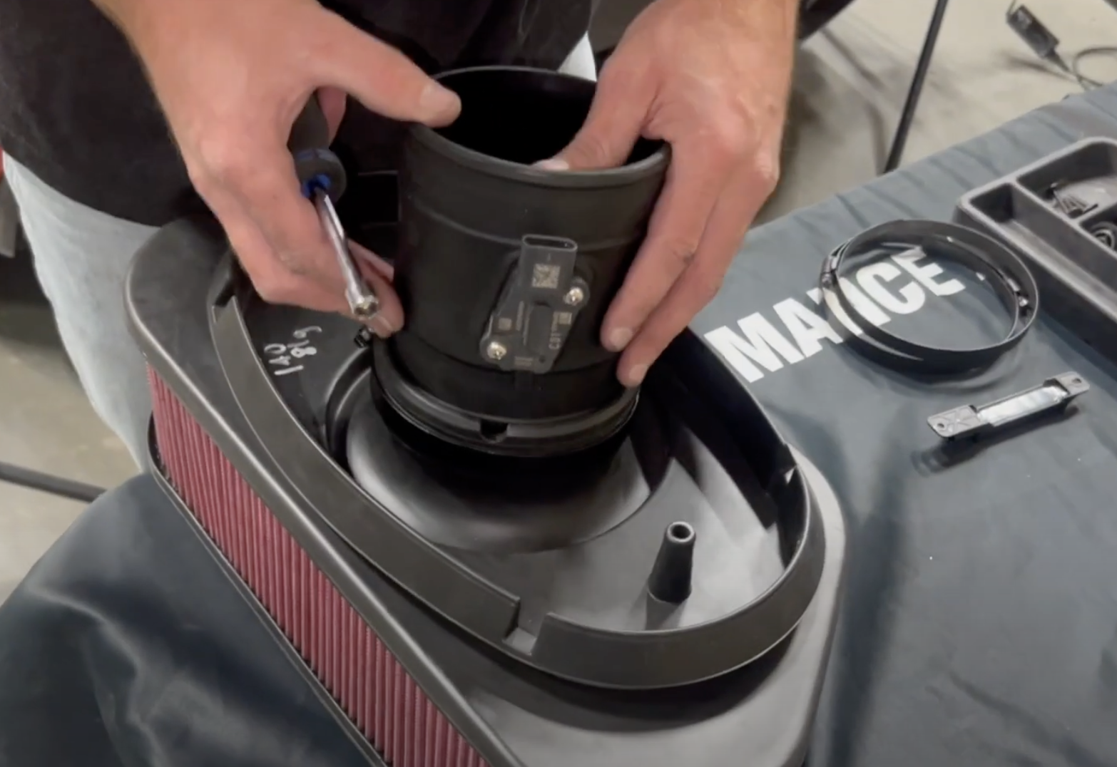
Remove the maf sensor from the oem intake tube. Install the S&B maf gasket, plastic pad then oem maf sensor onto the S&B tube and secure down with the Phillips head screws.
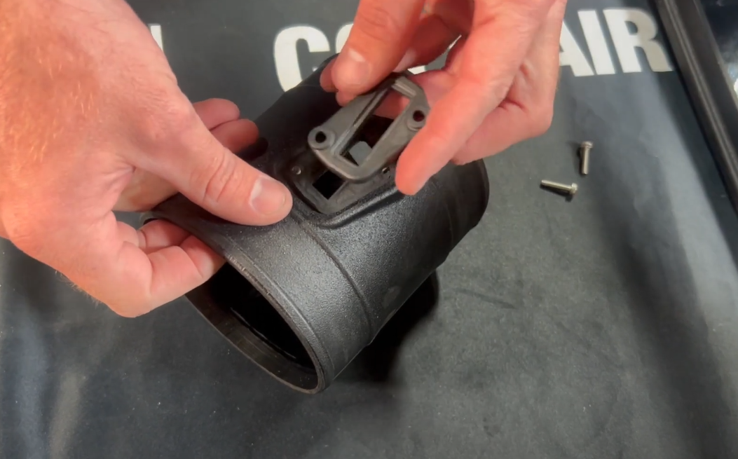
Install the JLT bracket and secure down with the OEM bolts
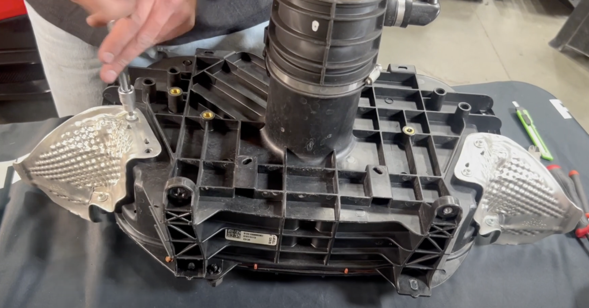
Remove the 10mm bolts that secure down the factory scoops. (on both driver and passenger side)
Install the aluminum compression limiters into the JLT scoops bolt holes and secure them down with the OEM 10mm bolts. They will be labeled left and right.
Install the included PCV fitting into the throttle body coupler with the hose clamp loose around the base of the fitting. Place the coupler on the throttle body to confirm the fitting lines up well to the quick connect on the car then tighten down the throttle body coupler.
Install the JLT tube into the air filter. The tube lines up with the notch in the filter.
Loosely install the hose clamps onto the side scoops.
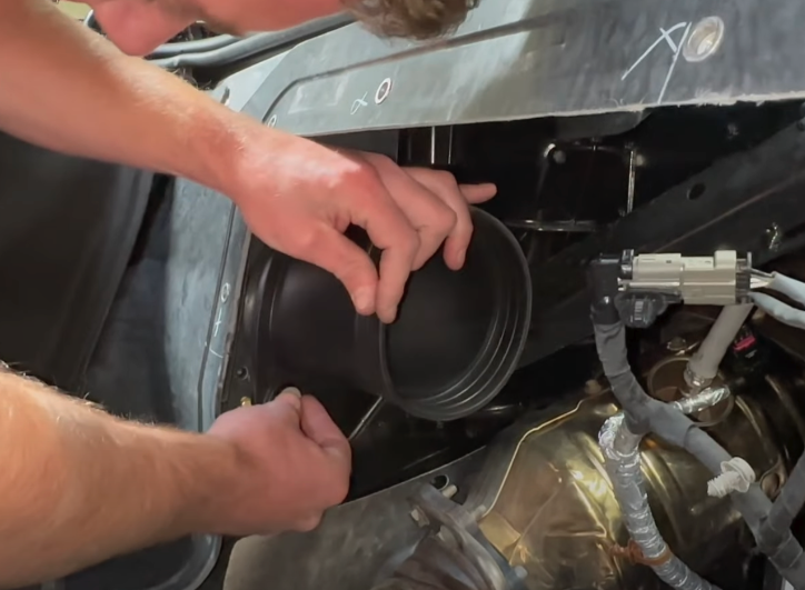
Install the JLT airbox into the vehicle.
Install the included 10mm bolts into the bottom on the airbox. Tighten down
Remove the temp sensor from the stock airbox then install on the JLT bracket under the box.
Reconnect the GPS antenna connector.
Tighten down the hose clamps that are on the scoops.
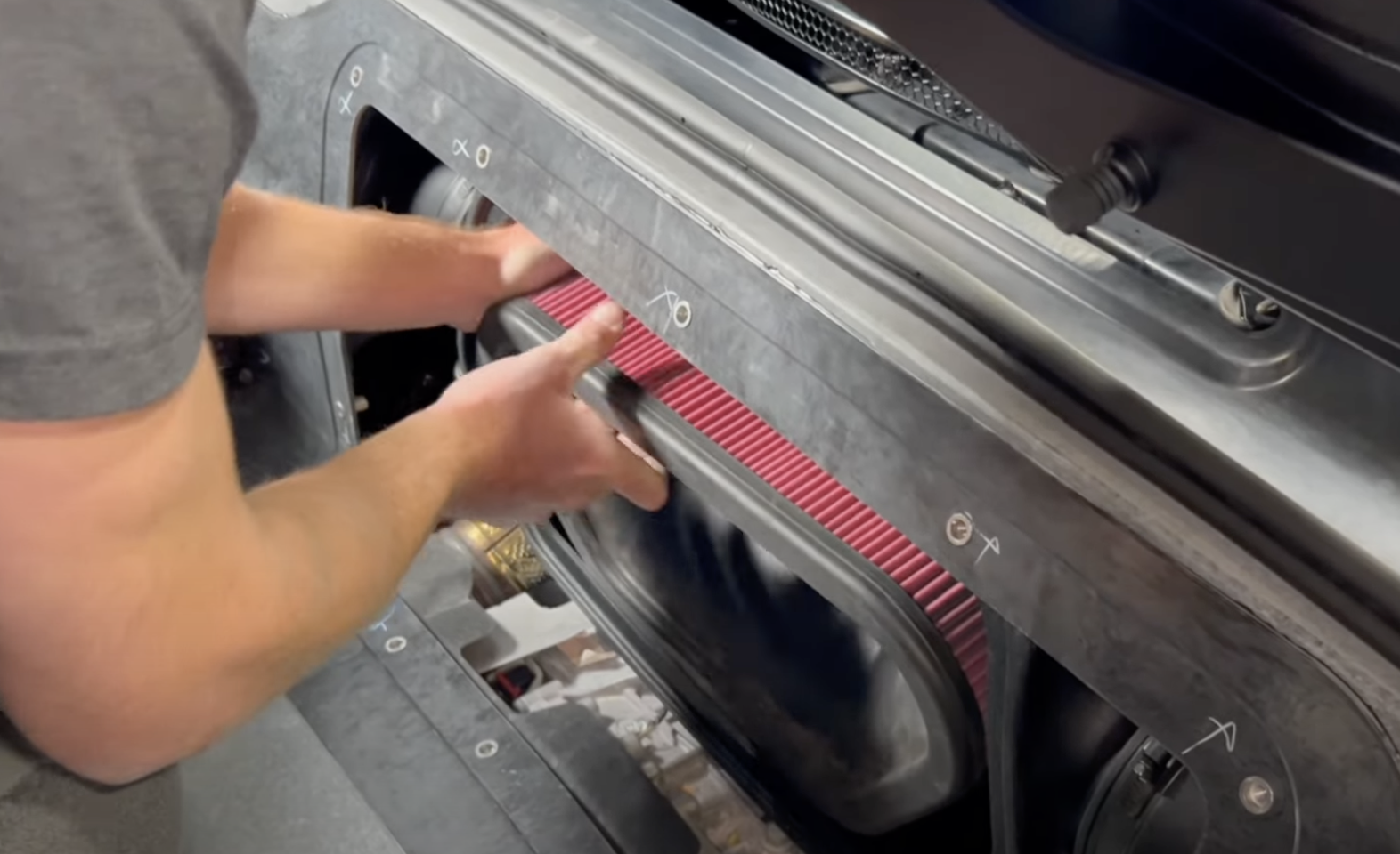
Install the filter into the airbox. Be sure the harnesses are tucked up out of the way before inserting the filter.
Reconnect the PCV quick connect
Tighten down the hose clamp on the coupler to the tube. You may need to pull on the tube slightly to get it into the coupler more.
Reconnect the MAF harness and canister vent. Then zip tie them out of the way.
Reinstall the coolant tank if you have a HCT.
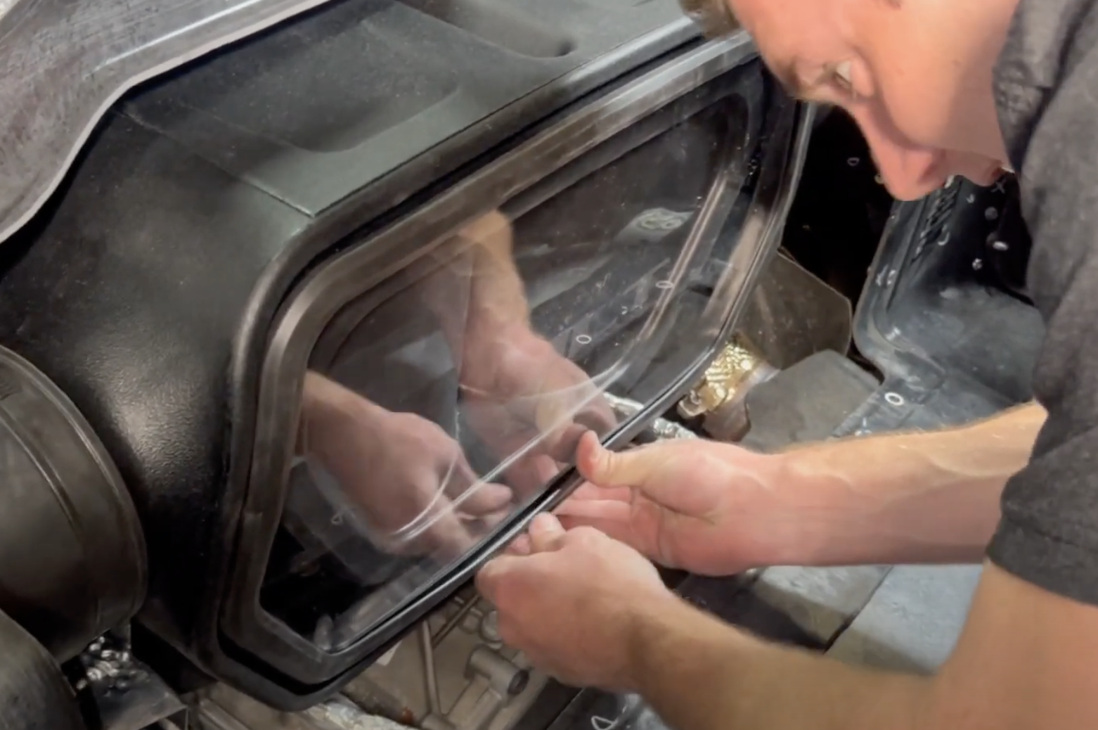
Snap in the JLT clear lid.
Reinstall the trunk cover, carpet, plastic plates and rivets.