Install Instructions for 86-1001

Before You Start

Thank you for purchasing your new S&B Filters Fuel Sending Unit. If at any time you need additional assistance with installation or have any other questions or comments, feel free to call our customer support team at 909-947-0015.

Our installation video walks you through the step by step installation process for the S&B Fuel Sending Unit.

Required Tools

  • ⅞” Wrench
  • Mallet/Hammer
  • Flathead Screwdriver

Step 1

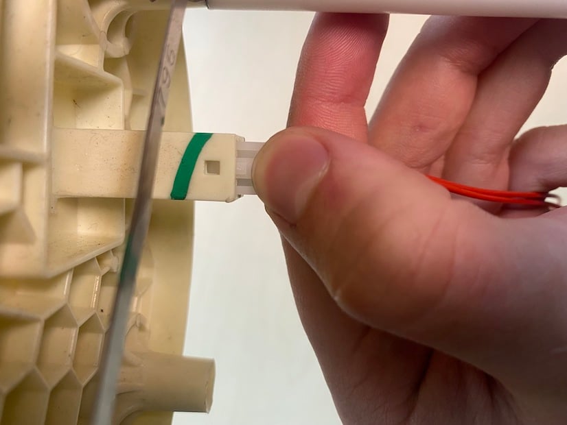
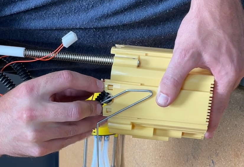
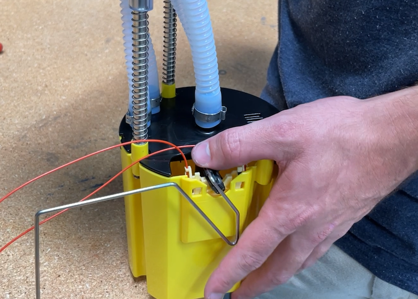
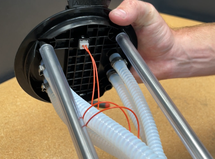
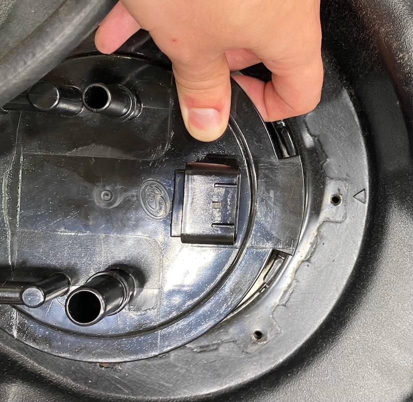
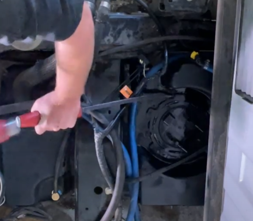
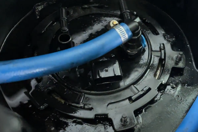
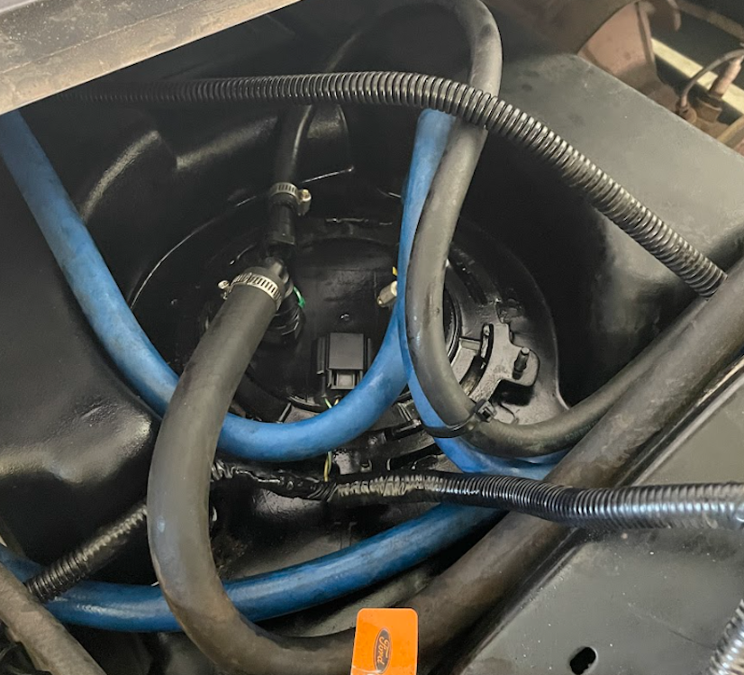
Begin by following S&B Tank instructions to drop the tank and remove the sending unit. Also, follow your lift pump installation instructions but DO NOT MODIFY your stock sending unit. WARNING: The S&B Sending Unit is optimized for aftermarket lift pumps set to 65 PSI, do NOT exceed 70 psi on your lift pump!

Step 2

With the stock sending unit removed from the tank, CAREFULLY remove the stock sending unit resistor card with the float by depressing the snap connector on the stock flange and pulling directly away from the flange.

Step 3

CAREFULLY depress the snap-in arms on the resistor card and slide it directly up and out of the reservoir.

Step 4

Install the resistor card and float into the reservoir of the S&B sending unit. Verify the resistor card is firmly snapped in and cannot move.

Step 5

Wrap the resistor card wire around the large hose a few times so that it cannot tangle with the float. Snap in the electrical connector into the flange of the S&B Sending Unit, verifying it cannot move.

Step 6

Insert the S&B Sending Unit into your fuel Tank. The center of the tab on the sending unit flange should line up with the arrow on the tank. Be careful to not damage the OEM float when putting it in the tank.

Step 7

Secure the S&B sending unit into the tank. Make sure the locking ring is oriented as it was on the OEM Tank so the sending unit guard will install without interference. Hammer the locking ring clockwise.

Step 8

Connect the factory return (elbow quick connect fitting with a blue tab) to the smaller straight nipple coming out of the flange and press the locking tab back in.

Sending Unit Connector Diagram

Use this diagram to help you with the next steps in connecting the fuel lines to your S&B Sending Unit.

Step 9

Connect your lift pump's return fitting (1/2" elbow quick connect) to the larger elbow nipple coming out of the flange and press the locking tab back in.

Step 10

Snap on the vehicle’s electrical connector to the sending unit.

Step 11

Press AI2714-00 (elbow quick connect with a green tab) into the tank side of your lift pump’s suction hose and tighten a hose clamp around it. Connect it to the large straight nipple on the sending unit, pressing in the locking tab.

IMPORTANT NOTE: If you already have a fitting installed on this end, cut it out to insert the quick connect. If your lift pump uses ½” fuel line for suction, use AI1039-19 (⅝” fuel hose) and AI2739-00 (⅝” to ½” brass reducer) to adapt the suction line to fit the quick connect.

Determine Your Lift Pump Type

The type of lift pump you have will determine the next steps:
If your lift pump has JIC fittings for swivel hose connections, follow steps 12 to 14.
If your lift pump has male quick connect hose fittings and a provided wye fitting, skip to step 15 to set up the Venturi power line. The wye fitting supplied with your lift pump is necessary for installation! You will not be using the brass tee fitting that comes with the S&B Sending Unit.

Step 12

Unscrew the ‘to engine’ fitting and ‘return’ hose (not the fitting) if they are already connected to your lift pump. Wrench matching your lift pump’s fittings.

Step 13

Apply the supplied thread sealant to the NPTF, or the long side, of AI2691-00 (brass tee fitting) and hand tighten. Use a ⅞” wrench for the last turn and angling the tee off towards the frame of the truck.

Step 14A

Press AI2760-00 (3/8" elbow quick connect) into one end of AI2722-01 (⅜” push lock fuel hose) and AI2716-00 (3/8" push lock JIC swivel) into the other end of the hose. Quick connect to the flange and screw the fitting to the tee along with the "To Engine" and "Return Lines" for your lift pump. Skip to step final checklist.

Note: Only use clean fuel hose to power the venturi so that your S&B Sending Unit performs correctly!

Step 14B

Step 15

Cut a section of AI2722-01 (⅜” push lock fuel hose) and press AI2738-00 (½” to ⅜” brass reducer) into the other end to adapt to the ½” venturi line coming from the wye fitting supplied by your lift pump manufacturer.

Note: Only use clean fuel hose to power the Venturi so that your S&B Sending Unit performs correctly.

Final Checkllist

This final checklist is very important.
1. Make sure all quick connectors are locked in.
2. Prime your lift pump according to your manufacturer’s instructions.
3. Check for leaks before reinstalling the tank according to S&B instructions.

If you have any questions, call or text us at 909.675.1313.