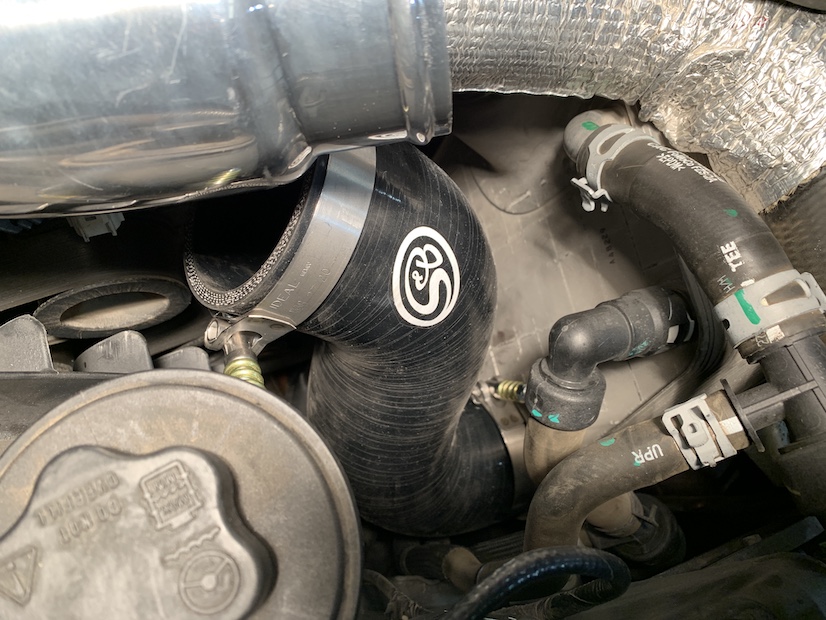
Step 1
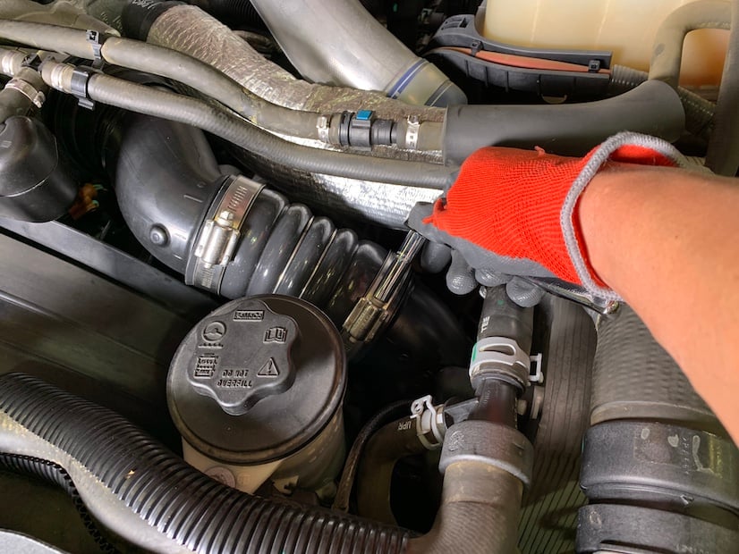
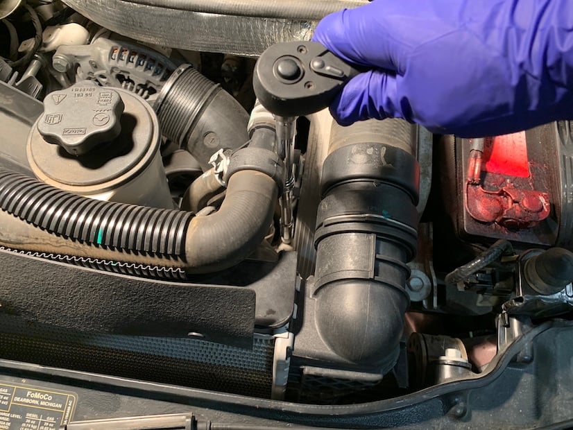
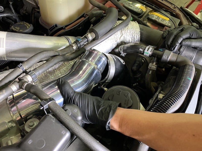
Loosen the upper hose clamp of the Charge Air Cooler (CAC) outlet hose. Loosen the second one closest to the Intercooler.
VEHILCE FITMENT: 2011-2016 6.7L Powerstroke, Ford, F250/F350/F450
DEVICE NAME: INTERCOOLER PIPE
This Charge Air Cooler Pipe Kit may not fit with the following aftermarket parts installed:
● Aftermarket Intercooler
● Aftermarket Radiator and/or Coolant Hoses
● Aftermarket Fan or Fan Shroud
● Aftermarket Power Steering Fluid Reservoir
● Aftermarket Hood
When removing any turbocharger air intake system components, make sure to cover any open ports to prevent any debris from entering the system. All components need to be inspected and cleaned (if necessary) prior to assembly and installation.
Note: Approximate Install Time: 1 Hr 00 Mins for Kit Installation.
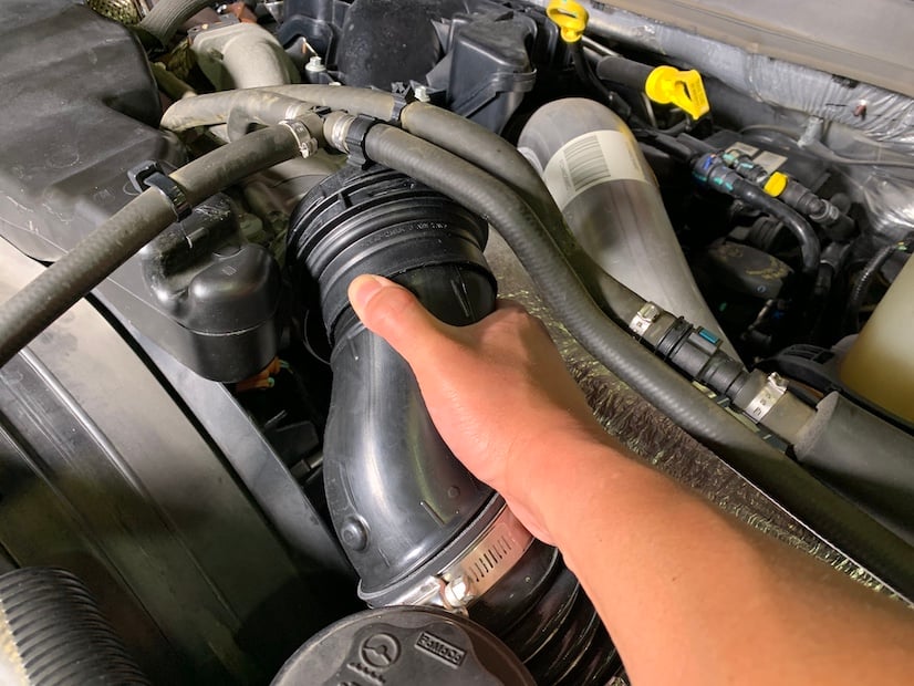
Loosen the upper hose clamp of the Charge Air Cooler (CAC) outlet hose. Loosen the second one closest to the Intercooler.
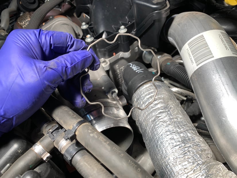
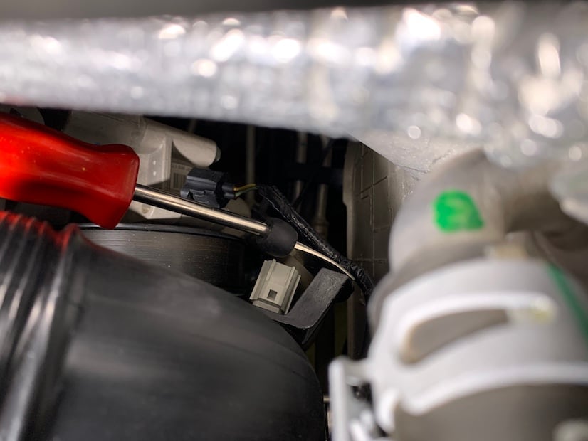
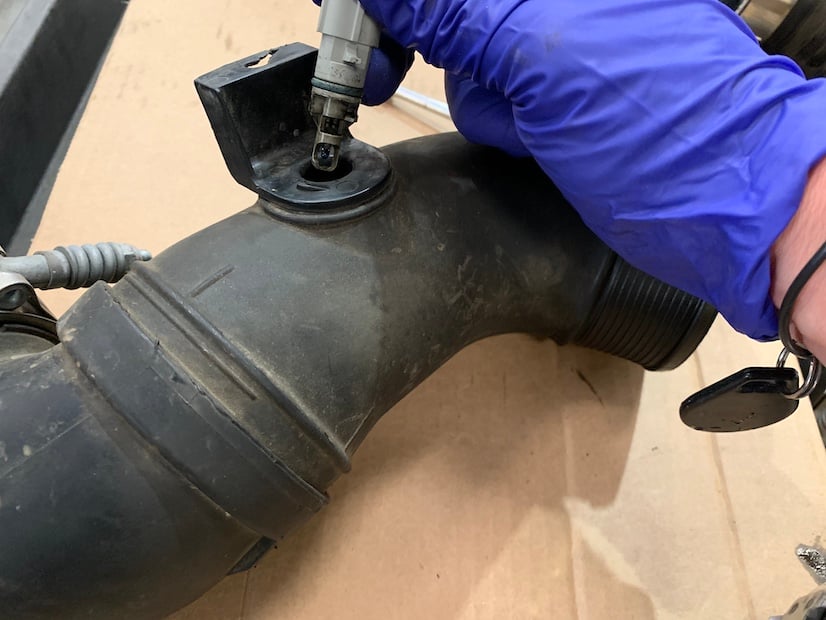
Using a Pick, locate the split in the Spring Clip and carefully remove the Spring Clip from the upper plastic CAC pipe.
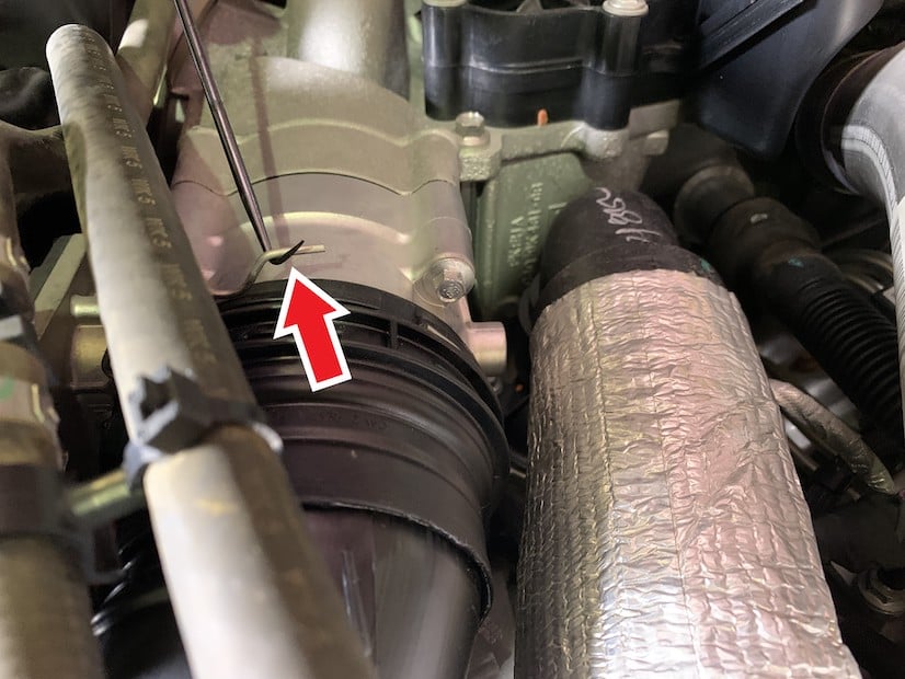
Working your way around, place the Spring Clip over the plastic and on to the throttle assembly for now.
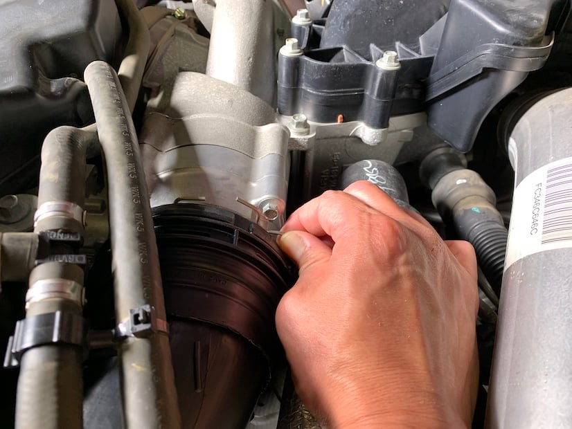
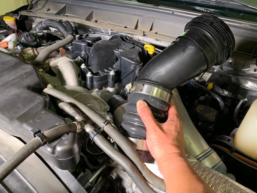
Slide the upper plastic CAC pipe off the throttle assembly and remove it from the vehicle.
Remove the Spring Clip from the throttle assembly and save it for use in Step 13.
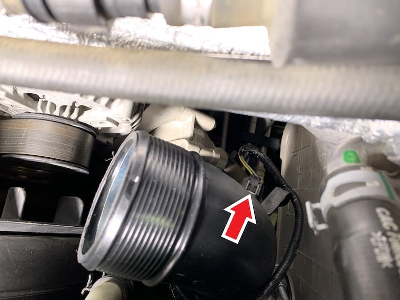
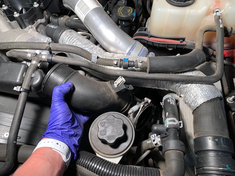
Remove the electrical connector from the Air Temperature Sensor located on the lower plastic CAC pipe. Depress the clip and pull it off.
Remove the Temp Sensor harness retainer from the lower plastic CAC pipe.
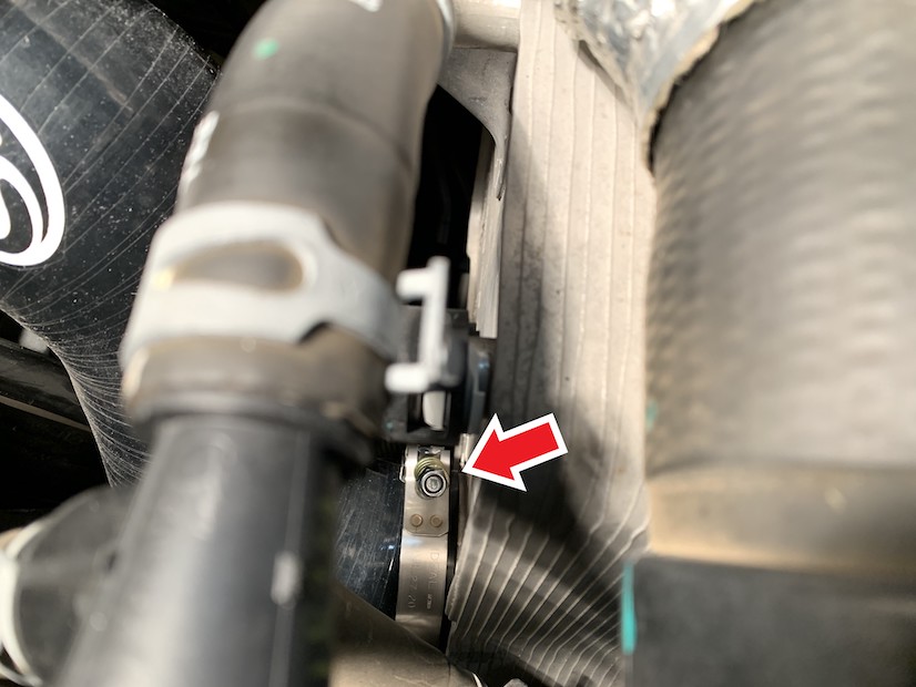
Loosen the lower hose clamp of the CAC outlet hose.
Slide the hose off the intercooler outlet and remove the lower plastic CAC pipe from the vehicle.
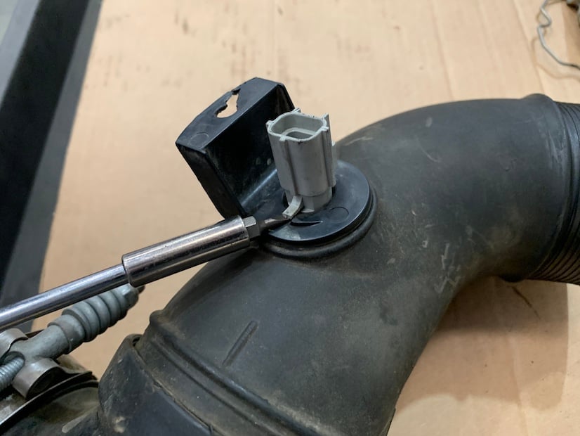
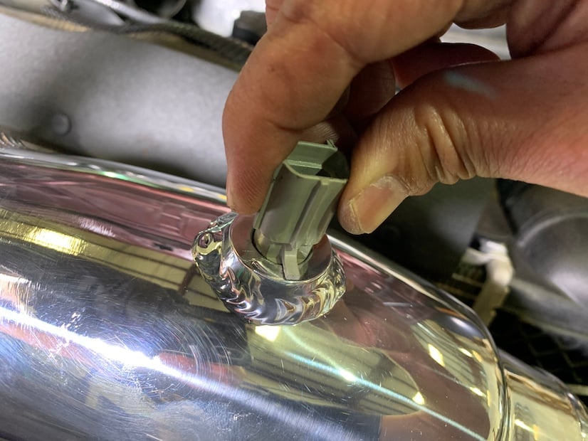
Remove the Temp Sensor from the lower plastic CAC pipe. Use a Small Flat Blade Screwdriver to gently lift the Temp Sensor tab above the locking ramp, then twist (counter clockwise) and pull out the Temp Sensor.
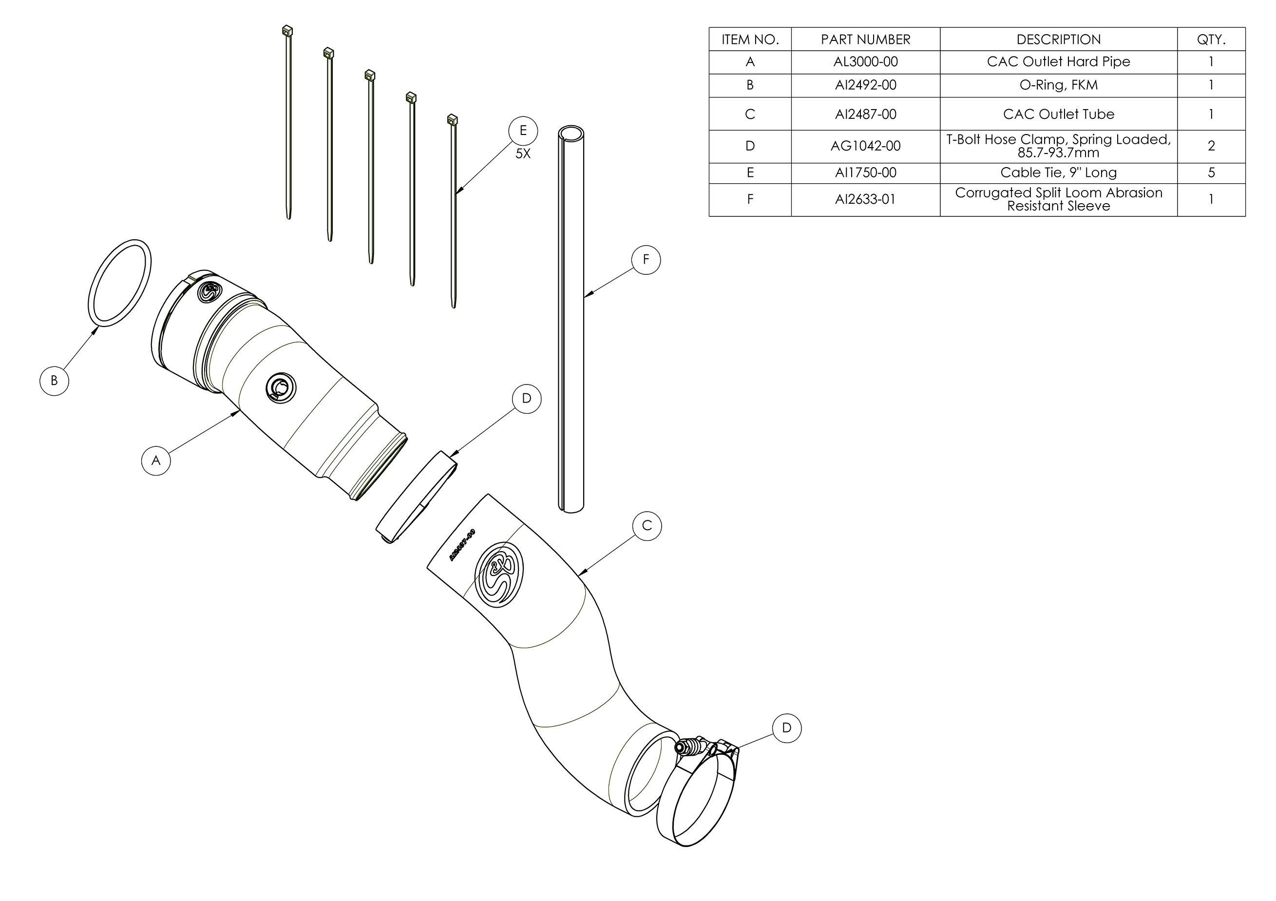
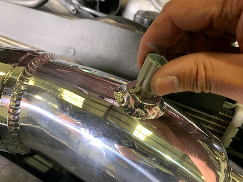
Insert the Temp Sensor into the CAC Hard Pipe (A) with the Temp Sensor tab resting on top of the boss and in front of the locking ramp as shown below.
Twist the Temp Sensor clockwise until the tab goes over and is locked by the locking ramp.
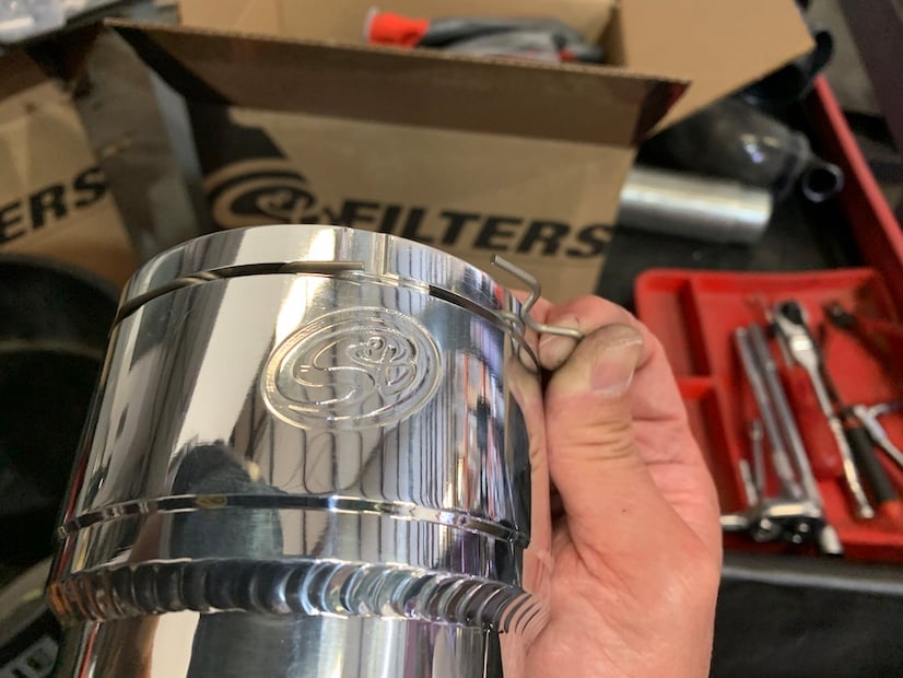
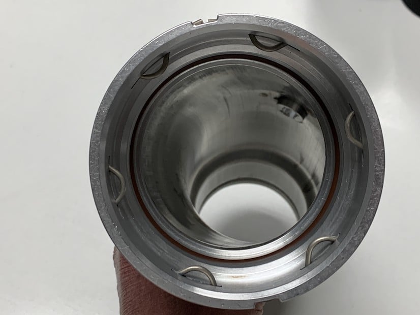
Install the Spring Clip from Step 5 into the clip groove on the CAC Hard Pipe (A).
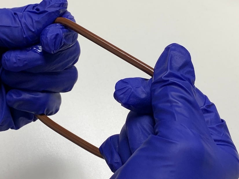
Stretch the O-Ring (B) by hand while adding a thin coat of clean diesel engine oil to the O-Ring. Work your way around the entire O-Ring, gently stretching it as you go. After stretching, verify that the outside diameter of the O-Ring touches all around the inside of the o-ring groove of the CAC Hard Pipe (A) as shown below. If the O-Ring feels loose in the o-ring groove, gently stretch the O-Ring by hand once more.
Add a thin coat of clean diesel engine oil around the outside diameter of the throttle assembly.
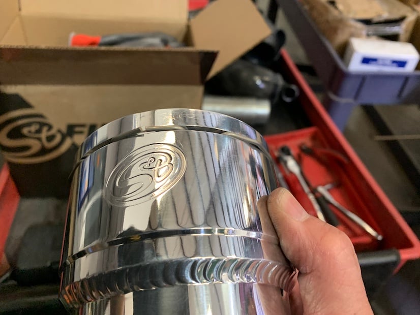
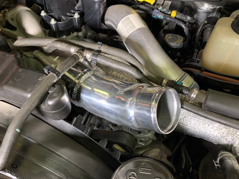
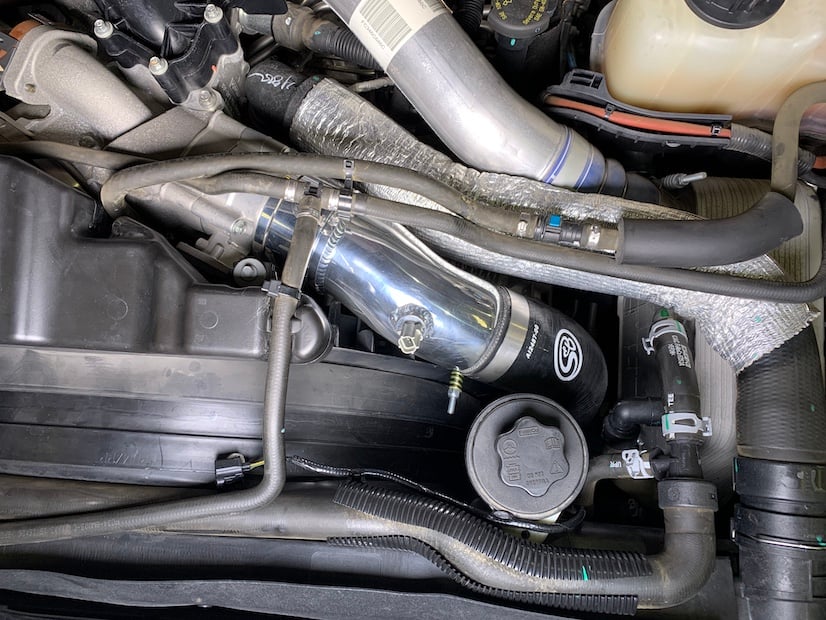
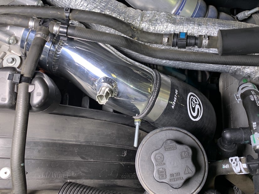
Install the CAC Hard Pipe (A) onto the throttle assembly until the Spring Clip snaps into place on the throttle assembly. Rotate the CAC Outlet Hard Pipe so that the hose end is pointed upwards as shown.
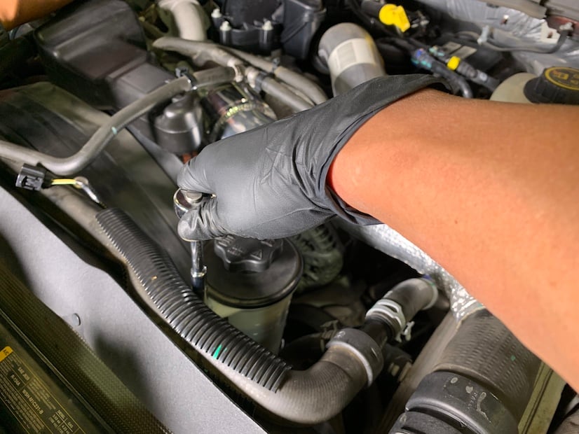
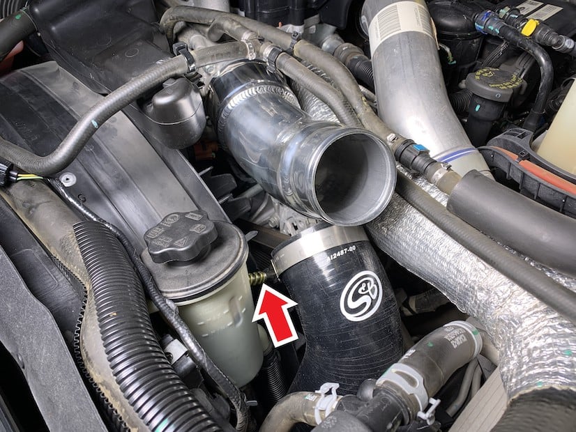
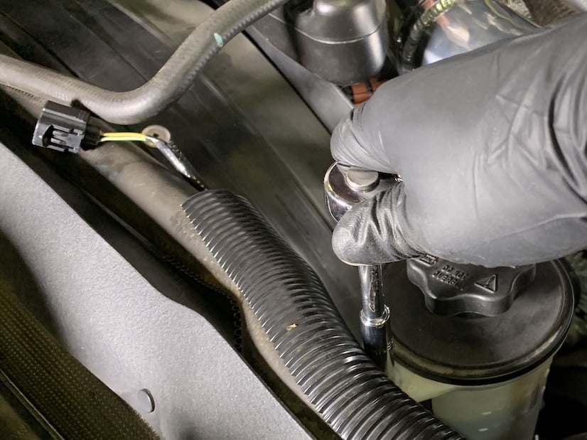
Remove the screw holding the power steering reservoir and set the screw aside.
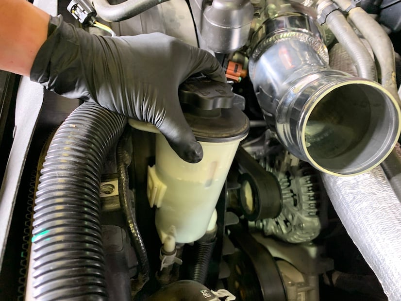
Lift the power steering reservoir from the support slot and carefully leave it off to the side while keeping it upright. This will give you more room when you install the CAC Silicone Hose (C).
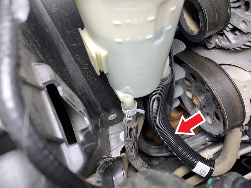
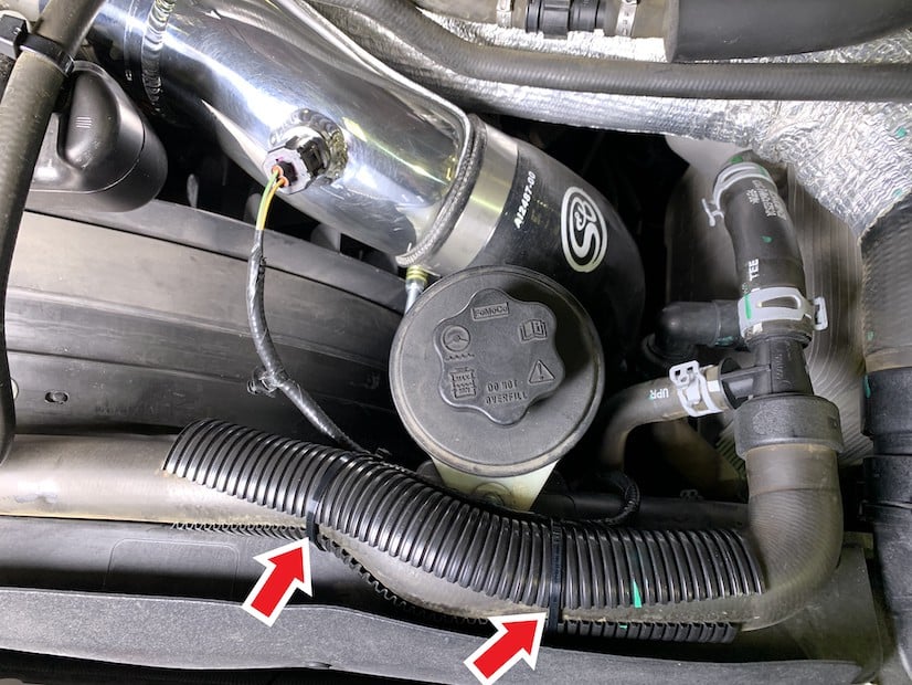
Pull and remove the stock split loom sleeve from the larger diameter power steering reservoir hose.
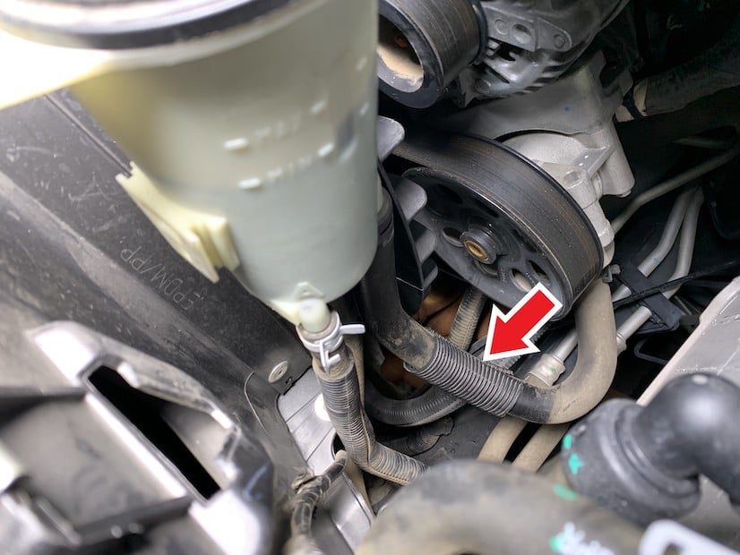
Install the Split Loom Sleeve (F) over the large diameter power steering reservoir hose as shown.
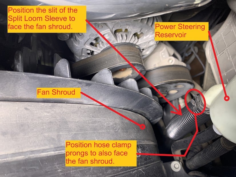
Make sure the Split Loom Sleeve (F) is up against the hose clamp of the power steering reservoir hose and that the slit is facing the fan shroud as shown. Also rotate the reservoir hose clamp so that the prongs are also pointing towards the fan shroud. To reposition the reservoir hose clamp, simply squeeze the prongs with pliers to loosen, rotate the clamp to position, and then release the clamp prongs.
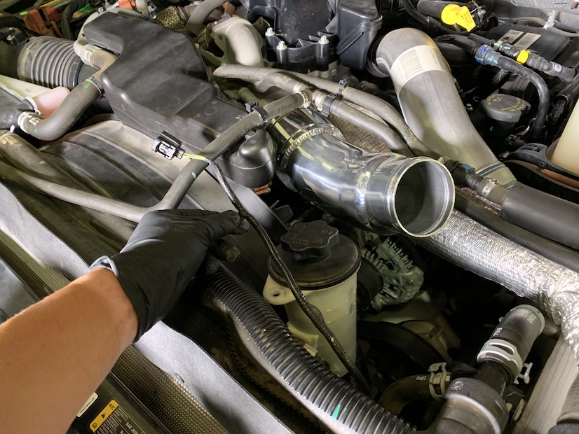
Move the Temp Sensor electrical harness away from the intercooler and temporarily drape it across the top of the power steering reservoir.
Install the T-Bolt Hose Clamp (D) onto both ends of the CAC Silicone Hose (C). On the end without the logo, have the spring and nut pointed up towards you as shown below. On the end with the logo, install the T-bolt Hose Clamp (D) with the spring and nut underneath and pointed towards you as shown below. Leave both T-Bolt Hose Clamps loose for now.
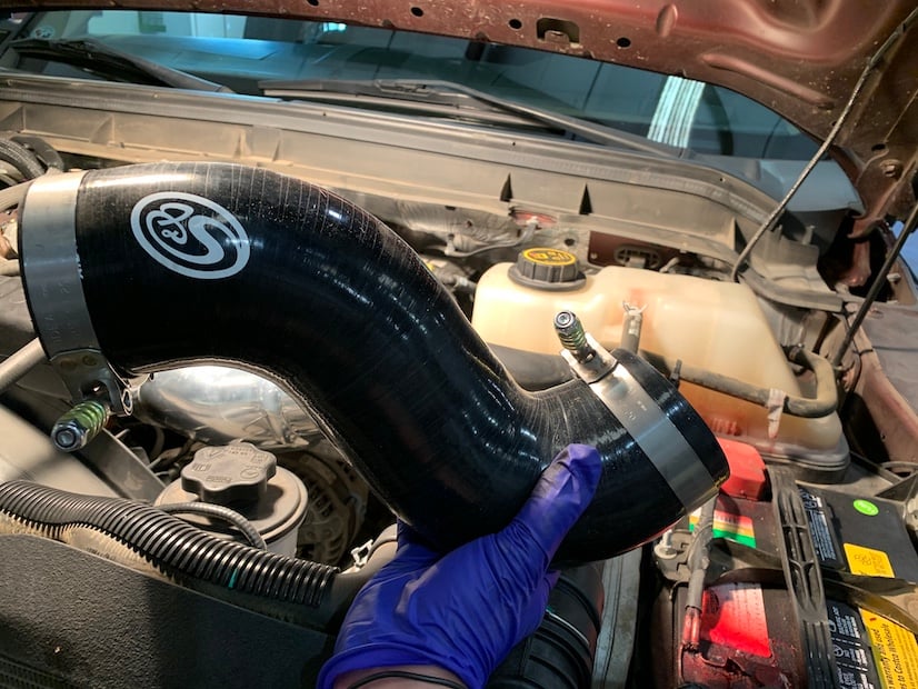
Install the CAC Silicone Hose (C) with the T-Bolt Hose Clamps into the vehicle with the logo end on top and the other end attaching to the Intercooler outlet. Leave the T-Bolt Hose Clamps loose at this time.
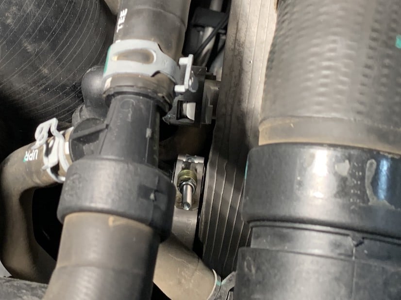
The lower T-Bolt Hose Clamp (D) should be positioned so that the spring and nut are pointed towards you and accessible from above as shown below.
The upper T-Bolt Hose Clamp (D), should be positioned so that the spring and nut are underneath and pointed towards the power steering reservoir as shown.
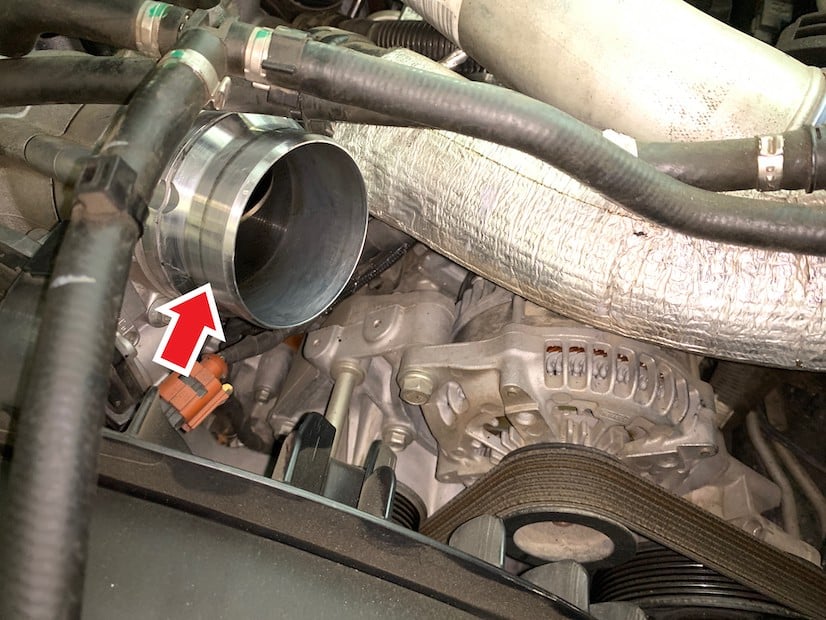
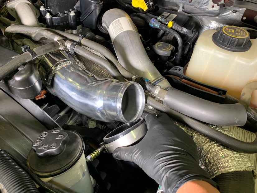
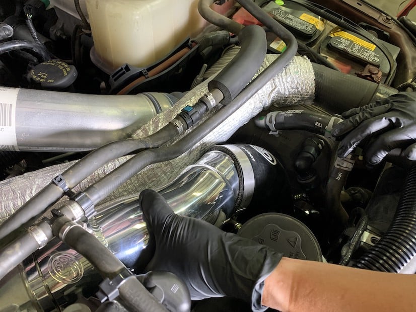
Rotate the CAC Hard Pipe (A) and pull the CAC Silicone Hose (C) onto the end of the Hard Pipe. As you continue to rotate the Hard Pipe, the Silicone Hose will slip over the Hard Pipe into position as shown.
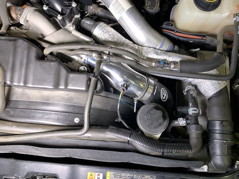
Put the power steering reservoir back in the support slot and check for clearances all around the CAC Hard Pipe (A) and CAC Silicone Hose (C). Rotate the CAC Hard Pipe to adjust the clearances making sure the CAC Hard Pipe and Silicone Hose are far enough away from the power steering reservoir and other surrounding lines, hoses, and clamps.
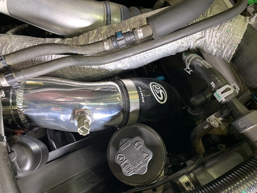
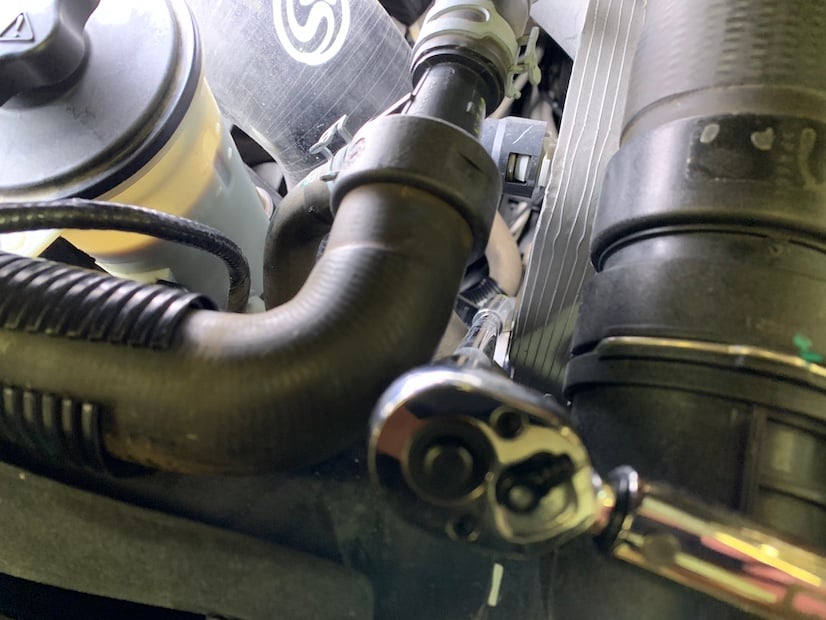
Once you have everything positioned properly, make sure the intercooler outlet is fully inserted into the CAC Silicone Hose (C) and then tighten and torque the T-Bolt Hose Clamp (D) to 75 in-lb.
After tightening the lower T-Bolt Hose Clamp (D), verify that the CAC Silicone Hose (C) is up against the intercooler, with the intercooler outlet fully inserted, and the T-Bolt Hose Clamp (D) about 1/ 8” from the end of the Silicone Hose as shown below.
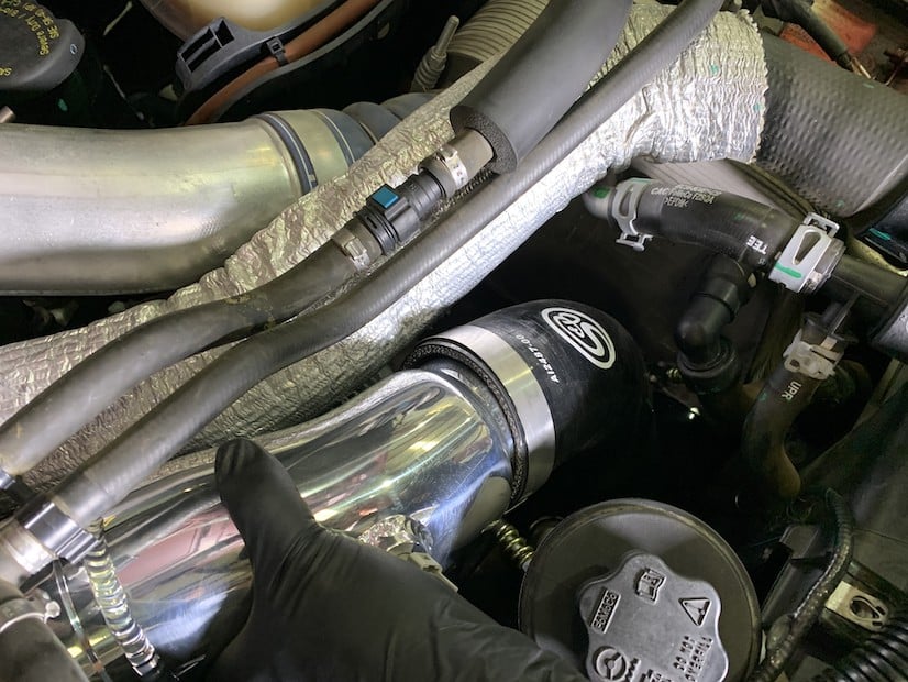
Make sure the CAC Hard Pipe (A) is fully inserted into the CAC Silicone Hose (C), and that the T-Bolt Hose Clamp (D) is positioned so that the spring and nut are not close to touching anything. Tighten and torque the T-Bolt Hose Clamp to 75 in-lb.
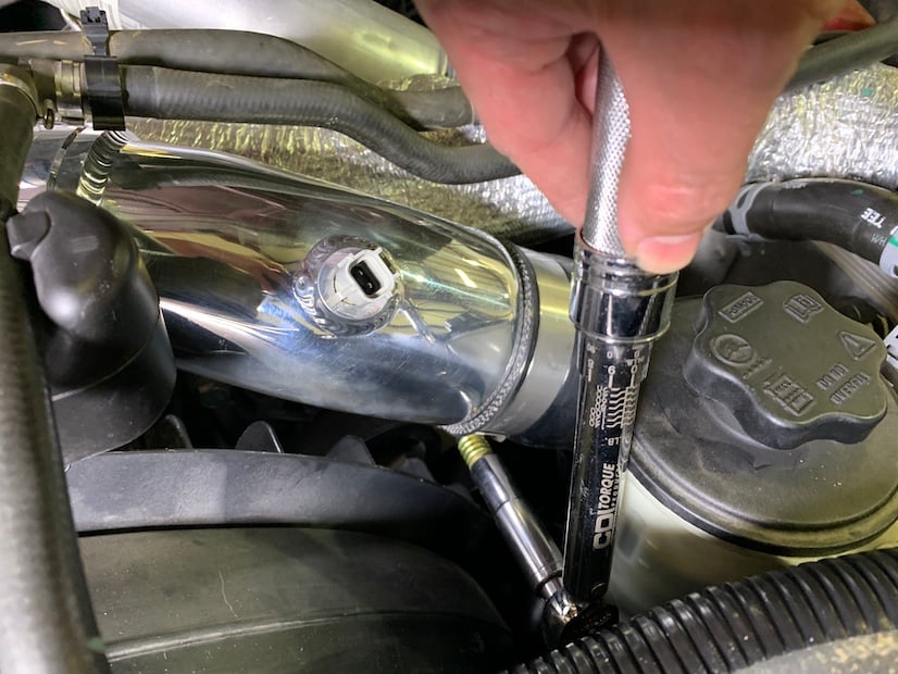
After tightening the upper T-Bolt Hose Clamp (D), verify that the CAC Hard Pipe (A) is fully inserted into CAC Silicone Hose (C) and the T-Bolt Hose Clamp (D) about 1/ 8” from the end of the Silicone Hose as shown below.
Replace the power steering reservoir support screw and tighten.
Reconnect the Temp Sensor to the harness.
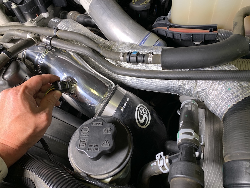
Secure the loose Temp Sensor harness with Cable Ties (E) to prevent the harness from rubbing during vehicle movement and vibration. Cut off the excess cable tie with a Wire Cutter.
Inspect your installation, make sure the kit is properly positioned with clearances around all the parts to prevent wear or damage to any parts during vehicle operation, movement, and vibration. Verify both T-Bolt Hose Clamps are tight and secured. Keep all stock parts in case you would ever need to reinstall the stock intake assembly. Affix the ID label near the CAC Outlet Kit. If you are an installer, give the owner the QR code for the Installation Instructions so that he/she is aware of the Maintenance and Operation procedures given in the beginning of the Instructions. Clean a flat visible surface under the hood and affix the enclosed CARB EO sticker for SMOG purposes. The installation is now complete.
Please affix the included CARB-approved EO label in an area under the hood. We recommend placing it on the radiator shroud, or the underside of the vehicle's hood near the S&B product.