Install Instructions for 76-7006

Before You Start

• Please read the entire installation manual before proceeding.
• Ensure all components listed on the following section are present.
• If you are missing any of the components, call our customer support at (909) 947-0015.
• Do not work on the vehicle while the engine is hot.
• Make sure the engine is turned off, the vehicle is in Park and the Parking Brake is set.

If your fans are not working as described in the instructions, please watch our fan troubleshooting video below. 

If you determine that part of your electrical system is malfunctioning, please contact S&B customer support for assistance.

Required Tools

  • 4mm Hex Key
  • 5mm Hex Key
  • 6mm Hex Key
  • ¾” Socket
  • 13mm Socket
  • 18mm Socket
  • 5/16” Nut Driver
  • Razor Blade
  • Mini Bolt Cutter or Heavy Duty Wire Cutter
  • Panel Popper or Flat Head Screwdriver
  • Small Phillips Head Screwdriver

STOP! IMPORTANT INFORMATION

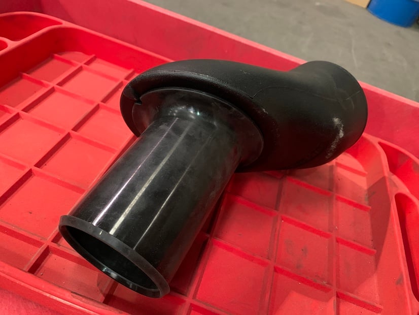
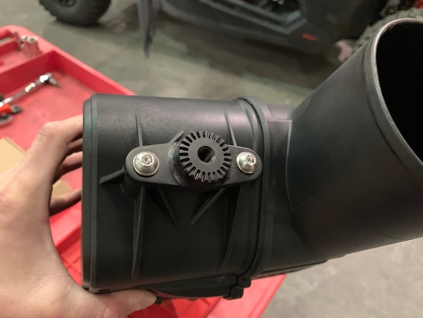
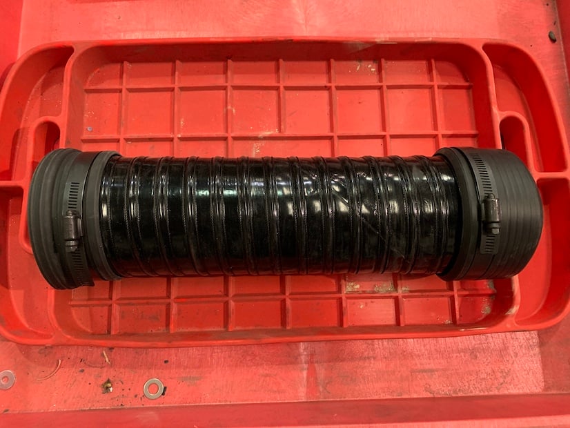
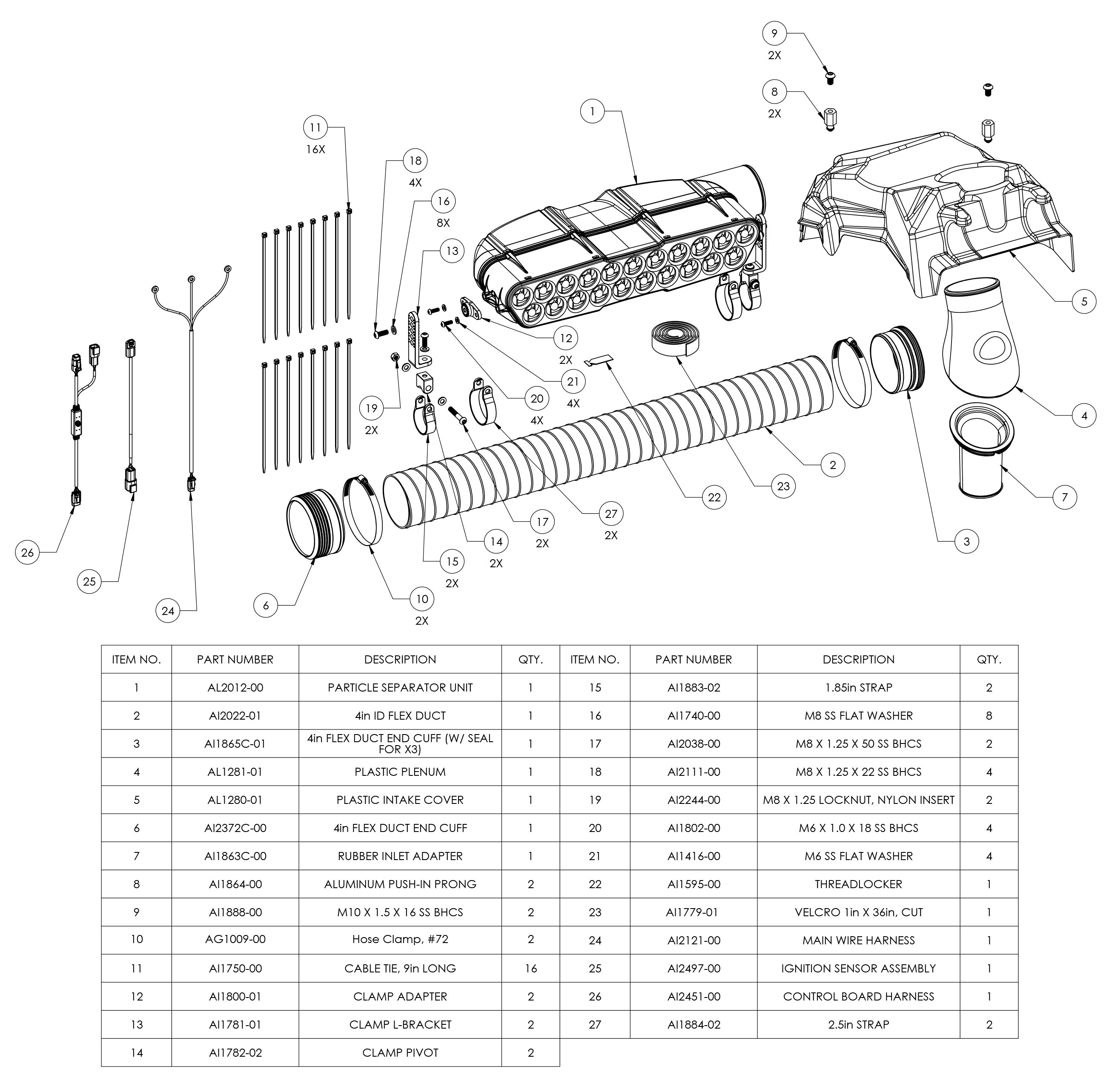
Warning: Prior to starting the install process, please check to make sure your kit includes the correct part #3 shown on the exploded view of the components as we have had a few customers get the wrong part. The inside diameter (larger side) of the step down coupler should be 4 inches as shown on this picture. If the larger side of the coupler included in your kit is 3.5 inches, you will need to contact us to get the correct replacement component for the kit which is part number AI1865C-01. You can request this replacement component via email at customerservice@sbfilters.com or by calling us at 909.232.8900.

STEP 1

Slide and tilt the front passenger seat as forward as possible to help in removing it. Remove the two rear nuts attaching the passenger seat to the frame of the vehicle.


STEP 2

Remove the two nuts and bolts securing the front of the seat to the frame of the vehicle. Then lift the seat up and out, completely removing it.


STEP 3

Lift up and remove the stock Air Intake Cover from the vehicle. After removing the stock cover, make sure the grommets didn’t come off with the cover or fall out of place.


STEP 4

Remove the CVT prefilter. You can do this by pulling up on the latch to release the tab and lifting up and out.


STEP 5

Install the silicone sleeve adapter (7) onto the S&B duct adapter (4). Make sure to line up the notch in the silicone sleeve with the mark on the plastic adapter.


STEP 6A

With the silicone sleeve adapter attached, slide the assembly into the CVT prefilter. The duct adapter must be facing in the direction as shown in the picture (pointing toward the rear of the vehicle when installed). Be sure that the lip on the underside of the silicone sleeve completely hooks onto the edge of the CVT prefilter inlet.


STEP 6B

STEP 7

Reinstall the CVT prefilter. When reinstalling, make sure that the tabs go into the slots on the back of the radiator support and are fully inserted. Press down on the part until it snaps into place.


STEP 8A

nstall the two push-in prongs (8) onto the S&B air intake cover (5). Apply the supplied threadlocker (22) to the threads of two M10-1.5 x 16 screws (9) and thread them into the push-in prongs through each of the two holes on the cover. The screw should be tightened from the top into the prong.


STEP 8B

STEP 9

Install the S&B air intake cover over the CVT pre-filter. Make sure the prongs go into the grommets. Press down on the cover directly over the two prongs to make sure they are seated properly.

Note: Determine where you would like to install the Particle Separator (1) on the roll cage, making sure you have enough room to fit the clamps and Particle Separator on the roll cage without any interference. Planning ahead will save you time during the install. Our clamps are adaptable enough to work around most accessories you may already have installed on the roll cage. The next Installation section shows how to install the Particle Separator on the lower bar but the steps of installation are the same if you decide to install the particle separator on the upper bar. Please note that the diameter of the “Lower Bar” and “Upper Bar” are different and require either 2.50” or 1.85” Clamp Straps respectively.

STEP 10

Install the Clamp Adapters (12) on the mounting bosses of the Particle Separator with the supplied M6-1.0 x 18 screws (20) and M6 washers (21). Apply threadlocker to the screw before tightening. You will do this on both sides of the Particle Separator unit.


STEP 11

Install the two Clamp Straps (2.50”) (27) onto the lower bar of the roll cage. Do not pull the ends of the straps open. Loosely wrap some plastic around the roll cage to prevent scratching, and push the straps onto the roll cage until they snap into place.


STEP 12

Install the clamp pivot bodies (14) onto the clamp straps with the supplied M8-1.25 x 50 screws (17), M8 washers (16), and M8 locknuts (19). Do not fully tighten the screws and locknuts. Leave the straps loose for final adjustments later in the install.


STEP 13

Install the L brackets (13) onto the clamp pivot bodies using the M8-1.25 X 22 screws (18) and M8 washers. Apply threadlocker to the screws before tightening. Ensure that the smaller side of the L bracket faces inwards toward the center of the vehicle. This step is especially important when mounting the separator on the lower bar since it is the only way the system will fit onto the vehicle.


STEP 14

Install the particle separator unit onto the vehicle by fastening the L brackets to the adapters previously installed onto the unit. Determine the proper angle to mount the clamp L-brackets to the clamp adapters based on the desired location for the Particle Separator. Make sure the ribs in the clamp L-brackets are properly seated inside the grooves of the clamp adapters. Do not attempt to rotate these parts once assembled. They are designed to lock into place once seated. Once you're satisfied with the position of the clamp L-brackets, apply threadlocker to the M8-1.25 x 25 screws, install the M8 washers, and tighten. Ensure that the L-brackets on both sides are pointed in the same direction and are aligned with each other.


STEP 15

Adjust the position of the particle separator unit so that everything sits as desired. Then tighten all of the screws and nuts associated with the roll cage clamps assembly so that the particle separator is completely fixed and does not move or rotate around the roll cage when shaken.


STEP 16

Insert one end of the flexible duct (2) onto the plastic duct adapter. Do not install the hose clamp #72 (10) or flex duct end cuff yet (6). Bring the other end towards the round clean air outlet of the Particle Separator to simulate the desired length of ducting. Note the amount of duct that needs to be cut. We recommend adding at least an extra inch to the length of the duct needed. The duct can always be cut shorter if desired. Remove the duct from the adapter and Particle Separator.


STEP 17A

Pierce the flexible duct using a razor blade, centered between the two-wire reinforcements. Cut all the way around, keeping the blade centered between the wire reinforcements the entire length of the cut. Use a mini-bolt or a heavy duty wire cutter to cut through the wire and duct. Use a pair of scissors to finish the cut and to even out any jagged edges.


STEP 17B

STEP 18

Insert one end of the flexible duct fully into the flex duct end cuff with a hose clamp #72. Make sure the hose clamp is seated in the groove of the flex duct end cuff. Leave the hose clamp loose. Insert the other end of the Flexible Duct fully into the flex duct end cuff with seal (3) with a hose clamp #72. Make sure the hose clamp is seated in the groove of the flex duct end cuff. Leave the hose clamp loose.


STEP 19

Install the flexible duct with the flex duct end cuff with seal onto the plastic duct adapter and the flexible duct end with the flex duct cuff onto the plenum outlet on the particle separator unit. Tighten each Hose Clamp #72. Make sure the hose clamp is seated in the groove of the Flex Duct End Cuff and check to make sure the duct will not pull off either of the openings.


STEP 20A

Remove the battery cover by removing the push-in rivets. Disconnect the negative (black) battery cable. Tools Required: panel popper or flat head screwdriver, 10mm socket

NOTE: Always disconnect the battery before doing any electrical modifications.

STEP 20B

STEP 21

Remove the center tunnel passenger side cover by pulling it out from the top. It may help to use a flat head screwdriver to unseat the clips on the inside of the panel.


STEP 22

Locate the battery busbar inside the center tunnel. Familiarize yourself with the 3 post locations, the top being ground (GND), middle positive (BATT), and bottom accessory (ACC). Remove the 3 nuts found on these posts.


STEP 23

Install the main wiring harness (24) with the ground (GND) wire in the top position, the 12v (BATT) wire in the middle position, and the key-on (ACC) wire in the lower position. Reinstall the nuts that were previously found on the posts.


STEP 24

Remove the back center panel from the vehicle by pulling out to unseat it from the grommets. This will give you access to the top of the engine and the wires connected to the spark plug coil packs which are needed in the following steps.


STEP 25

Locate the ignition sensor (25) and remove the top clip piece.


STEP 26

Install the ignition sensor onto the positive ignition coil wire (brown). Make sure that the top clip piece touches the bottom clip piece on the inside. It is recommended to use zip ties (11) on each side of the connector to ensure it does not slide up or down the wire during use. You may connect the sensor to any of the 3 ignition coils.


STEP 27

Route the end of the main wiring harness back through the center console area and the end of the ignition sensor harness forward and above the engine. Be sure that the ignition sensor harness does not rest on the engine, turbo, or any other hot/moving components.


STEP 28

Locate the control board harness (26) and familiarize yourself with it using the picture for this step. One side will have a single 3 pin connector that connects to the Particle Separator fans. The other end has two connectors: one square 4 pin connector that connects to the ignition sensor, and one flat 2 pin connector that connects to the main power harness.


STEP 29

Plug the square 4 pin connector on the control board harness into the connector on the ignition sensor and the 2 pin connector on the control board harness into the connector on the main wiring harness.


STEP 30A

Route the slack of the wiring harnesses so that they are hidden. We recommend bunching up the excess from the main wiring harness and zip tying it to the other wires under the center console tunnel. Zip tie the slack from the control board harness and ignition sensor to one of the flexible tubes found to the left and above the turbo, right behind the center console back cover. Be sure that the harnesses do not touch any hot or moving parts.


STEP 30B

STEP 31A

Connect the single 3 pin connector on the other side of the control board harness to the 3 pin location found on the bottom of the Particle Separator unit. We recommend routing the 3 pin connector up through one of the holes on the plastic shroud above the intercooler to connect it to the Particle Separator unit.


STEP 31B

STEP 32A

Reconnect the negative terminal on the battery and replace all panels that were removed in the installation process. Reinstall the passengers side seat to complete installation.


STEP 32B

You have now completed the installation for your new Particle Separator. To ensure that everything is installed correctly and there are no problems with any part of the electrical system, we need to run a test to verify the function of the whisper quiet fan technology system. 

Test the particle separator with these steps:

1. Turn the ignition to the key on position. The fans on the particle separator should be at 20% speed and should barely be audible.

2. Turn the ignition on. The fans should be at 50% speed and barely be audible over the engine idle noise.

3. Rev the engine to a constant 4000 rpm for 5 seconds and then take your foot off of the gas. The fans should build to and stay at max speed during the 5 seconds, and decelerate back to 50% speed 2 seconds after you let your foot off of the gas.

If your particle behaves as these tests describe, the installation is complete. If the separator does not act as described, please watch our electrical system troubleshooting video to determine the cause of the misbehavior.

Side Note

S&B recommends that you apply a layer of waterproof grease, such as made by Bel-Ray or Super Lube, on the inside flange of the stock air filter to keep dust from bypassing the seal.


Ongoing Maintenance

Your Particle Separator requires very little if any maintenance depending on where you drive; however, you should check to make sure that none of the openings in front of the Particle Separators are blocked by mud or other debris each time you exit the UTV. You should also make sure the scavenge fan is operating properly. To do so, simply check to make sure the fan is still blowing out air (for about 15-20 seconds) when you turn off your UTV as this is a normal condition. If the fan is not blowing out air or the airflow seems lower than when you initially installed your system, please contact S&B tech support. To clean your Particle Separator, review the cleaning instructions below.