STEP 1
Remove the 4 screws securing the bed to the vehicle. Lift it up and out, twisting to get it around the vehicle’s side covers. T40 Torx
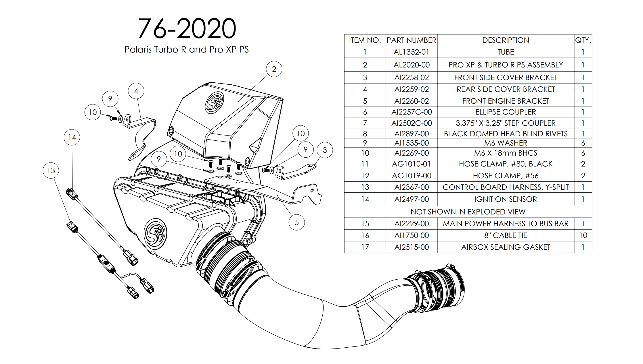
• Please read the entire installation manual before proceeding.
• Ensure all components listed on the following section are present.
• If you are missing any of the components, call our customer support at (909) 947-0015.
• Do not work on the vehicle while the engine is hot.
• Make sure the engine is turned off, the vehicle is in Park and the Parking Brake is set.
Remove the 4 screws securing the bed to the vehicle. Lift it up and out, twisting to get it around the vehicle’s side covers. T40 Torx

Remove the bolts and push in rivets connecting the rear driver side panel to the rest of the vehicle. T40 Torx and Panel Popper

Remove the push in rivet on the underside of the body panel to release it. Panel Popper

Remove the back half of both seats (Rear if 4 seater) by pressing the release button on the back of the headrest, then pull up and out.

Remove the 3 bolts and one push in rivet securing the body panels from the inside of the vehicle. T40 Torx & Panel Popper


Disconnect the rubber grommet holding the gas line to the body panel by pressing it back through the plastic.

Remove the side body panel assembly. Note that there are two clip-in attachments at the bottom below the gas cap that will need to be pressed out while removing the body panels, as well as possible additional fasteners that vary based on model.

Cut out the 3 pages of templates you received. If you received your kit before we started adding the templates, please call or email customerservice@sbfilters.com so we can send you the templates/trimlock.

Align the 2 pieces each template and tape together. The words/lines are duplicated to show where it should be taped together. Please see the how the same text/line is on both pieces.

Line up the longer template with the fender body panel. Use the screw hole in the body panel to help line up. Trace the template with a pen.

With a reciprocating saw or wheel, cut the trim line. Cover the area around the trim line with painters tape to prevent any scratching.

Clean up area that was cut then install the trimlock over the area that was cut. You will need to cut off the excess trimlock

Install the next template onto the panel. Tape down, trace the exposed inside area, tape off, then cut.

Remove both of the rear access panels by turning each of the 6 quarter-turn fasteners counterclockwise and pulling out.

Remove the intake tube from the vehicle by loosening the hose clamp connected to the airbox, as well as the hose clamp connected to the side cover. 5/16” drive


Remove the two bolts securing the side cover to the vehicle. 10mm socket


Remove the side cover from the vehicle. Lifting up the rear plastic will make this much easier.


Remove the OEM bolt on the underside of the vehicle next to the suspension column, and loosely fasten the front Particle Separator bracket with the same screw. T40 Torx

Install the Front Scoop Bracket to the frame using one bolt removed from Step 10. Also, hand tighten the two installed brackets using (5) supplied M6 screws and washers. 10 mm socket


Install the Front Scoop Bracket to the frame using one bolt removed from Step 10. Also, hand tighten the two installed brackets using (5) supplied M6 screws and washers. 10 mm socket

Install the rear scoop bracket using the bolt removed from the previous step and (1) supplied M6 screw and washer for the side cover, hand tightening. 10mm socket

Make sure the Particle Separator has clearance with the suspension, and tighten each bracket at every mounting point while holding the back of the Particle Separator up so it is level.

Install the step coupler with the smaller end on the airbox and tighten the supplied hose clamp. 5/16” driver

Install the S&B Intake tube and tighten the supplied hose clamps at both ends. 5/16” driver


Locate the ignition sensor and remove the top clip piece. Phillips screwdriver

Install the ignition Sensor onto the positive ignition coil wire placing it about 1” away from the connector. Make sure that the top clip piece touches the bottom clip piece on the inside. Use Zip ties on each side of the connector to ensure it does not slide up or down the wire during use.The clips around the orange wire won't be gripping the orange wire tightly. It just needs to be around the wire. Phillips screwdriver


Route the sensor harness towards the front of the vehicle, under the airbox and pass the connector through the opening underneath the frame on the right side. Use zip ties to secure the harness to the frame away from engine components.

Locate the Y connector harness and familiarize yourself with it using the picture for this step. One side will have a single connector that connects to the scavenge fan from the PS. The other end has two connectors: one square 4 pin connector that connects to the ignition sensor, and one flat 3 pin connector that connects to the main power harness.

Plug the square 4 pin connector on the Y harness into the connector on the ignition sensor that you pulled through the frame earlier (see another view of how the wire is routed in this picture).

Connect the single 3 pin connector on the other side of the Y harness into the connector from the Scavenge fan coming from the main Particle Separator unit.

Bundle the remaining length of the Y harness if necessary for your vehicle application, and zip tie it to the chassis as shown with the connector that goes to the main harness pointing down.

For 4-seater applications, fold the rear seats forward and remove the rear panel by removing the 11 screws and one push pin on the passenger side. Then pull up and remove the panel.

Remove cupholders, both front and rear if applicable, by simply pulling up and out. This will allow for easier wire harness routing.

For 4-seater, route the harness back through the center console and out where you removed the back seat panel.

Remove the 6 screws securing the front passenger side center console panel so you are able to pull the bottom forward, but not fully remove. Make sure to remove the ones next the seat as well. T40 Torx


Remove the front in-dash tray by using a pry tool or screw driver to pop out both sides under the handles, then pull up and out.

Route the connector end of the main power harness through the hole in the dash down through to the passenger side and pull enough through to route the rest of the harness.


Pull the center console side panel out from the bottom and insert the connector underneath it as shown. You can grab a hold of it from the cupholder opening. Once it is through, push the rest of the harness into the center console under the panel as well.


For 4-seater, route the harness back through the center console and out where you removed the back seat panel.


Pull the harness to the back under the frame and sway bar.

Connect the main harness to the Y-splitter harness end. Use zip ties to secure the bundle you made before as well as any loose harness from the ignition sensor.

Connect the pulse connector to one of the plug-ins in the dash.

To ensure that everything is installed correctly and there are no problems with any part of the electrical system, we need to run a test to verify the function of the whisper quiet fan technology system.
Test the particle separator with these steps:
1. Turn the ignition to the key on position. The fans on the particle separator should be at 20% speed and should barely be audible.
2. Turn the ignition on. The fans should be at 50% speed and barely be audible over the engine idle noise.
3. Rev the engine to a constant 3000 rpm for 5 seconds and then take your foot off of the gas. The fans should build to and stay at max speed during the 5 seconds, and decelerate back to 50% speed 2 seconds after you let your foot off of the gas.
If your particle behaves as these tests describe, the installation is complete. If the separator does not act as described, please watch our electrical system troubleshooting video to determine the cause of the misbehavior. Ensure each electrical connection is snapped and the wires are in a suitable location away from hot or moving components.

Remove the airbox lid by undoing the latches and pulling off. Remove the current lid seal by simply pulling it out. Install the new airbox lid seal provided by pressing it into the channel in the lid. Make sure the yellow side is facing up. Reinstall the airbox lid.


Reinstall/fasten rear seat panel, center console panels, center dash tray, and cup holders using the removed OEM hardware.

Reinstall the rear body panel assembly with the OEM hardware removed before. Remember to pull the rubber seal holding the gas fill cap back into the plastic.

Reinstall the bed into the vehicle. Make sure all OEM screws are reused (you will have (1) 10 mm bolt from Step 10 leftover) and that the connections are secure.

S&B recommends that you apply a layer of waterproof grease, such as made by Bel-Ray or Super Lube, on the inside flange of the stock air filter to keep dust from bypassing the seal.
Your Particle Separator requires very little if any maintenance depending on where you drive; however, you should check to make sure that none of the openings in front of the Particle Separators are blocked by mud or other debris each time you exit the UTV. You should also make sure the scavenge fan is operating properly. To do so, simply check to make sure the fan is still blowing out air (for about 15-20 seconds) when you turn off your UTV as this is a normal condition. If the fan is not blowing out air or the airflow seems lower than when you initially installed your system, please contact S&B tech support. To clean your Particle Separator, review the cleaning instructions below.