Install Instructions for 75-5175

Before You Start

This intake kit may not fit with the following Aftermarket Parts installed:

Body Lift or Lowering Kit

Custom Hood

Throttle Body Spacer / Upgrade 


Please read the entire product guide before proceeding. 

  • Ensure all parts are present.
  • If you are missing any of the components, call our customer support at (909) 947-0015.
  • Do not work on your vehicle while the engine is hot.
  • Make sure the engine is turned off and the vehicle is in Park or the Parking Brake is set.


Required Tools

  • 8mm, 10mm, 11mm Wrench/Socket
  • 16mm Wrench
  • T20 Torx (Supplied)
  • Phillips Screwdriver
  • Flat Blade Screwdriver 

STEP 1

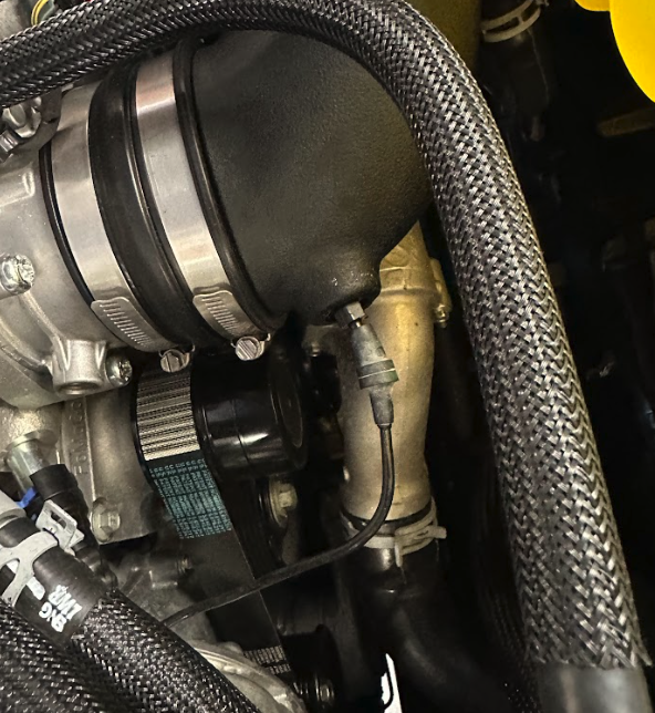
With the ignition switched off and the parking brake set, disconnect the negative battery cable on the driver’s side.

IMPORTANT: Failure to disconnect the battery for a minimum of 2 hours may cause the Check Engine Light to illuminate upon completion of the installation or subsequent operation. DO NOT SKIP THIS STEP!

STEP 2

Remove the push rivets on the scoop with a flathead. 

STEP 3A

Disconnect the IAT sensor and the two christmas tree connectors connecting the harness to the air box. 

STEP 3B

STEP 4

Loosen the hose clamp at the throttle body. 


STEP 5

Disconnect the push on barb located near the throttle body. 

Step 6a

You will need to remove the hose fitting from the driver side valve cover. In order to remove this we recommend using a pick tool to lift the yellow tabs in the sides of the black connector, then remove the black fitting from the fitting on the valve cover. 

If unable to remove the black connector doing the above method, you can also cut the lower end (where the yellow tabs interlock) of the black fitting using a wire cutter.

Helpful How-To Video:

To disconnect the Ford quick-connect on the valve cover, please watch our youtube video starting at 2:15. 

https://youtu.be/w31qbJunz6Y?si=Sq9cWXx1mdZ2AEjf&t=135

Step 6b

Now it's time to remove the yellow fitting. To do so you can cut the lower sections where the Factory male fitting locks into the yellow female fitting.

STEP 7

Remove the screw holding the stock intake to the vehicle. 

STEP 8

Remove the stock intake from the vehicle. 

STEP 9

Remove the IAT sensor from the stock intake. To remove, use a screwdriver to pry under the lock as shown in the picture, then twist counterclockwise. 

STEP 10A

Clip in the IAT extension harness, then zip tie the harness to the side on the engine bay as shown in the picture. 

STEP 10B

STEP 11

Install the IAT grommet onto the S&B intake tube. 

STEP 12

Thread the small insert into the S&B intake tube. The insert is NPT so there will be some thread showing. 

STEP 13

Install the bigger fitting into the tube. The insert is NPT so there will be some thread showing. 

STEP 14

Unwrap the S&B filter (B) and get it installed into the air box. 

STEP 15

Install the grommet (I) and shoulder bushing (S) onto the S&B air box. 

STEP 16

Install the front inlet scoop (A) onto the S&B air box using the provided push rivets (G). 

STEP 17

Install the OEM IAT sensor into the S&B intake tube. Make sure the tab goes over the ramp as seen in the picture. 

STEP 18

After the S&B tube is fully assembled, install the tube into the filter. Then install the hose clamp and tighten down (not all the way). 

STEP 19

Install the coupler (C) and hose clamps (O) onto the throttle body. 

STEP 20

Drop the assembled airbox into the vehicle and install it onto the coupler at the throttle body. Then fully tighten down all the hose clamps. 

STEP 21

Reinstall the OEM bolt and fender washer. Then fully tighten down. 


STEP 22

Re-install the hose onto the S&B barb located on the intake tube. 

STEP 23A

Now, go ahead and orientate the CCV tube insert (U) with the angled cut on the insert facing the supercharger. Then insert it into the CCV quick connect fitting (M) on the intake tube (D).

STEP 23B

Clip in the quick connect extended CCV.

Step 23C

Go ahead and clip in the IAT Sensor (Red Arrow). Then, please zip-tie the IAT Sensor harness extension (Q) to the coolant hose (Green Arrow). 

STEP 24

Remove the protective cover on the S&B clear lid (K), then install the lid into the lid seal (J). 

STEP 24 (IMAGE 2)

STEP 25

Snap the assembled S&B clear lid onto the air box. 

STEP 26

Install the provided panel poppers (F) into the scoop to retain to front core support.   

Step 27

Reconnect the negative battery cable to your battery.

Verify all connections points are secure and tight.

Your install is now complete.