Install Instructions for 75-5163

Before You Start

Note:
This intake kit may not fit with the following Aftermarket Parts installed:
Body Lift or Lowering Kit
Custom Hood
Throttle Body Spacer / Upgrade
Aftermarket turbocharger

Please read the entire product guide before proceeding.

  • Ensure all parts are present.
  • If you are missing any of the components, call our customer support at (909) 947-0015.
  • Do not work on your vehicle while the engine is hot.
  • Make sure the engine is turned off, negative battery cable is disconnected, and the vehicle is in Park or the Parking Brake is set.


Required Tools

  • 10mm Socket + Socket Wrench, Driver, or Wrench
  • 5/16” or 8mm Nut Driver or Socket and Driver
  • 7/16th or 11mm Socket or Wrench
  • ¼” Nut Driver or Socket and Driver
  • Flat Head Screwdriver
  • Phillips Screwdriver
  • Panel Popper
  • Pliers
  • Knife, Cutting Tool

STEP 1

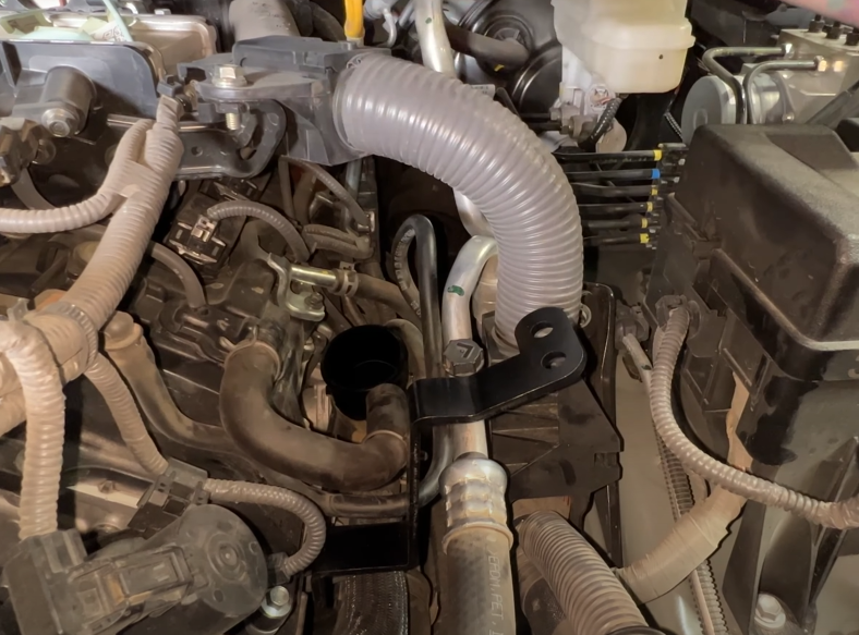
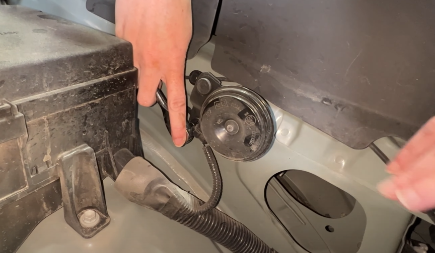
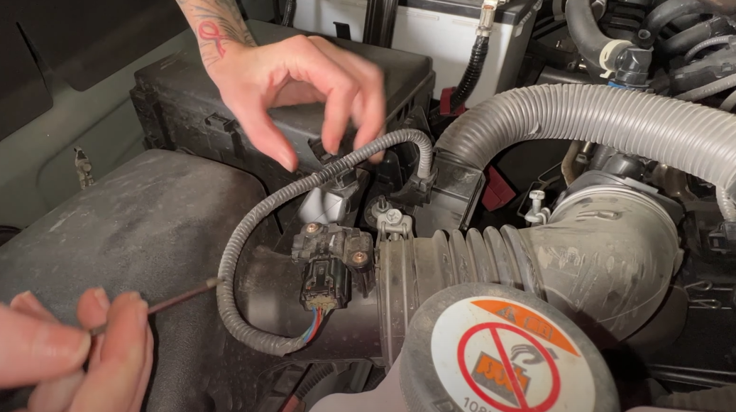
With the ignition switched off and the parking brake set, disconnect the negative battery cable on the battery. Note: Failure to disconnect the battery may cause the CEL to be illuminated upon installation and subsequent operation completion. Do not skip this step!

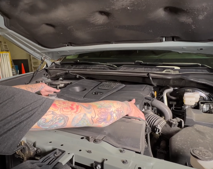
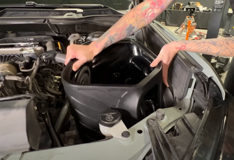
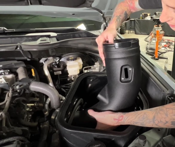
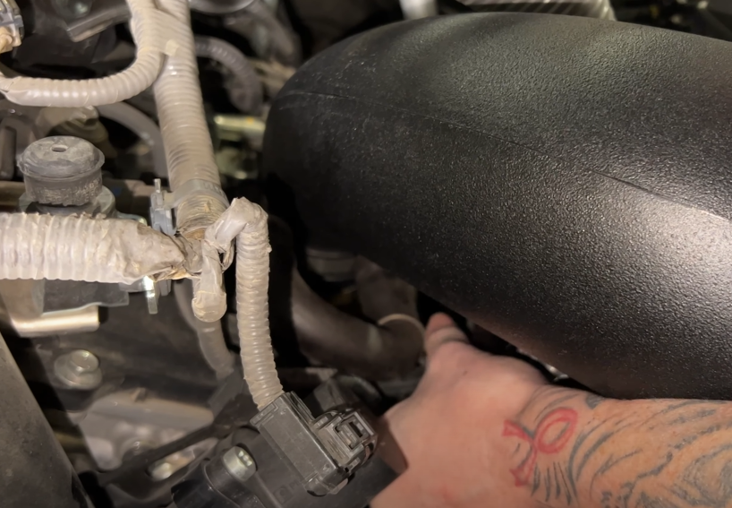
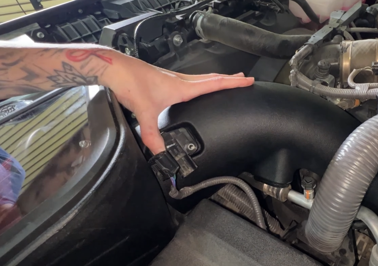
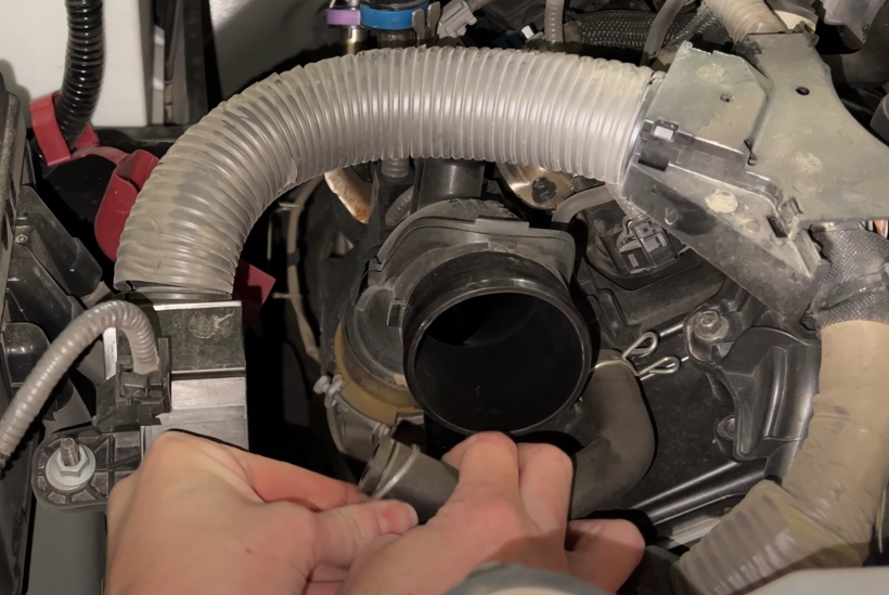
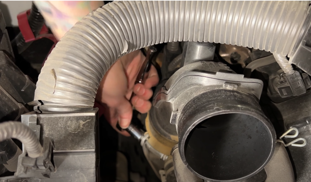
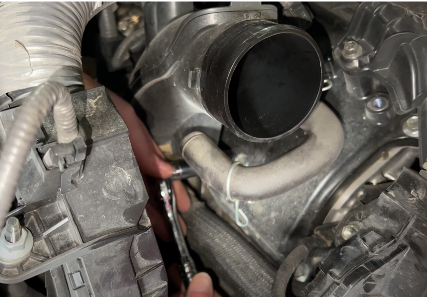
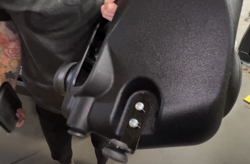
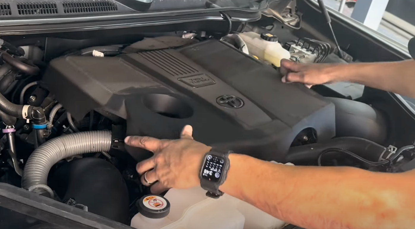
After disconnecting the battery, remove the engine cover.

STEP 2: DRIVER SIDE

Loosen the bolts on the hose clamps for the driver side intake tube

STEP 3

Disconnect the electrical connection to the MAF sensor, as well as the wire harness from the air box. Once done, loosen the two hose clamps on the intake tube (10 mm socket).

Tip: You will need body clip removal tool to disconnect the MAF wire harness.

STEP 4

Remove the driver-side Air box and engine Air intake hose.

STEP 5

Remove the CCV hose and mounting bolt from the driver-side lower air intake tube.

STEP 6

Remove the bolt connecting the OEM mounting bracket to the tube. Keep OEM bracket bolt for S&B Bracket installation. Next loosen the hose clamp connecting the intake tube to the turbo.

Tip: You'll need an 8mm socket to do this.

STEP 7

Unclip the line from the intake tube and remove the lower intake tube

STEP 8

Remove this bolt and put it aside as it will be reused with the S&B mounting bracket.

STEP 9

Install the S&B mounting bracket with the bolt you just removed.

STEP 10

Install 3 grommets into the bottom of the S&B air box.

Tip: If grommets weren't included in this kit, you can use the OEM grommets.

STEP 11

Determine if you want to install box plug (R) to the driver-side box (A). Check the testing results to determine the setup that you desire.

STEP 12

Install the tube seal (Q) and the the fender seal (C) onto the box.

STEP 13

Install the step down coupler(X) onto the intake tube. Please note the direction the hose clamps are pointing. This will make tighten the clamps easier when the tube is installed.

STEP 14

Install the MAF Sensor adaptor (J) into the intake tube.

Tip: You will need to do this for both Driver & Passenger side intake tubes.

STEP 14b

Insert the CCV insert (AD) into the barb fitting on the intake tube. Make sure the insert is pushed in all the way as shown. 

STEP 15 (RECOMMENDED)

Remove the bolt for the horn to make the install of the intake box easier.

STEP 16

Install the intake box making sure the grommets line up with the body

STEP 17

Insert the intake tube through the box and rotate the tube to connect the tube to the turbo inlet.

STEP 18

Re-install the OEM bolts to secure the bracket to the vehicle and secure the hose clamp on the turbo inlet.

Tip: You will need an 7/16th or 11mm socket to tighten the OEM bracket bolts down.

STEP 18b

Verify that the driver side hose clamps on the coupler connecting the intake tube to the turbo inlet are secure.

STEP 19

Install the PCV hose onto the S&B intake tube and secure with the clamp. Then use the included hex head bolts (AA) to secure the intake tube to the bracket.

STEP 20

Remove the MAF Sensor from the OEM intake tube. Take the MAF sensor, MAF mount (T), MAF gasket (O), then use the included screws (P) to install the OEM MAF to the S&B intake. Reconnect the MAF sensor harness.

STEP 21

Install the filter (N) with #80 hose clamp (W) onto the intake tube (B).

STEP 22

Remove the from the clear lid (E) and install the silicone Lid Seal (F) around the outside edge of the clear lid (E). Then snap into the opening of the air box.

STEP 23: PASSENGER SIDE

Loosen the bolts, disconnect the clip holding the MAF harness and disconnect the MAF from the OEM intake tube. You can then remove the OEM air box from the truck.

STEP 24

Remove the PCV hose from the intake tube

STEP 25

Loosen the hose clamp on the turbo inlet.

STEP 26

Remove the bolt securing the intake tube. This bolt will be reused. You can now remove the intake tube from the vehicle.

STEP 27

Install the box mounting bracket (U) to the box with the provided hardware and rubber grommets. Install the tube seal and fender seal to the box and install the box plug if you decided to install the box plug on the driver side intake box.

STEP 28

Install the step down coupler onto the intake tube with the head of the hose clamps on the opposite side of the intake tube as the MAF with the clamps facing the passenger side body panel.

STEP 29

Install the passenger side bracket (K) onto the intake tube with the supplied washers (AB) and hex head bolts (AA).

STEP 30

Lift the intake box up and rotate the intake tube onto the turbo inlet.

Once the tube is installed onto the turbo inlet, take the OE head cover bolt and slide it through the bracket to the head cover in order to fully install the intake tube.

STEP 31

Install the PCV hose onto the S&B intake tube and secure with the clamp.

STEP 32

Re-install the MAF into the Passenger Side S&B intake tube with the MAF gasket (O), MAF mount (T) and included screws (P), then plug it back in.

STEP 33

Install the filter and tighten all hose clamps on the passenger side intake assembly.

STEP 34

Remove the lid film, install the silicone lid seal and install the lid onto the box opening.

STEP 35

Re-Install the MAF Sensor into the Passenger Side S&B intake tube with the MAF mount (T), MAF gasket (O) and included screws (P), then plug it back in.

STEP 36

Re-install your engine cover.

STEP 37

Re-install the horn on the driver side if you loosened it and double check to verify all your connection points are connected and tight. Next, reconnect the negative terminal to the battery. Your install is now complete.