Install Instructions for 75-5162

Before You Start

Please read the entire product guide before proceeding.

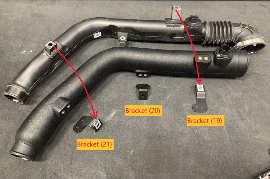
Ensure all parts are present.

If you are missing any of the components, call our customer support at (909) 947-0015.

Do not work on your vehicle while the engine is hot.

Make sure the engine is turned off and the vehicle is in Park and the Parking Brake is set.


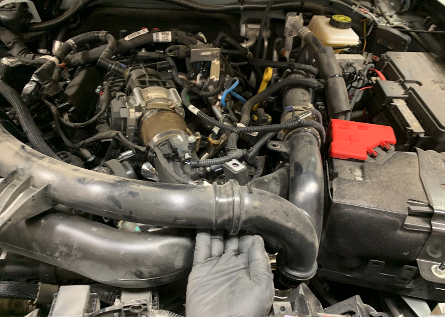
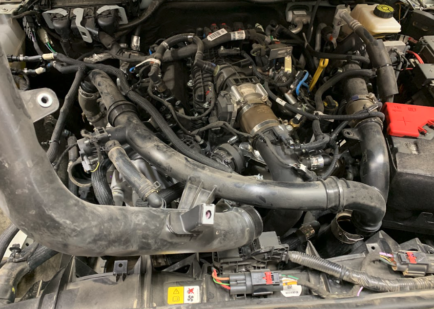
S&B FILTERS recommends that you keep your OE intake system in the event it is required in the future.


In order to maintain your warranty, all connections and components must be checked periodically for alignment and for proper tension on all connections. Failure to do so may void your warranty.


Use only S&B FILTERS cleaning and oil products to service your filter. Using any other brand oil and or cleaners on your S&B air filter may void your warranty


Periodically (during each engine oil change) Check the Following

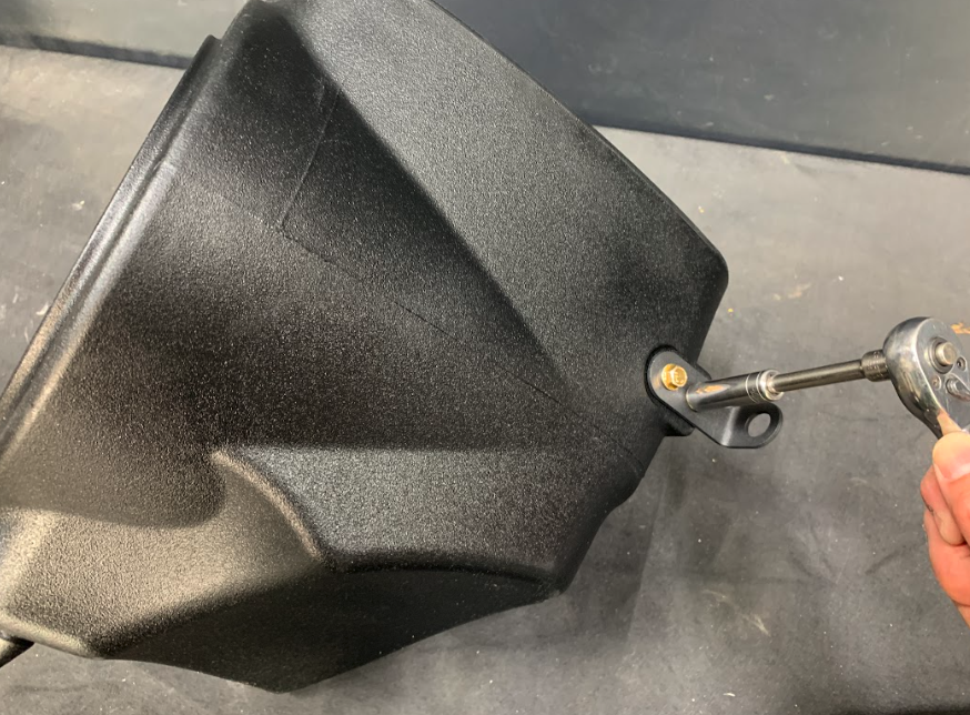
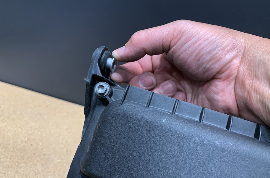
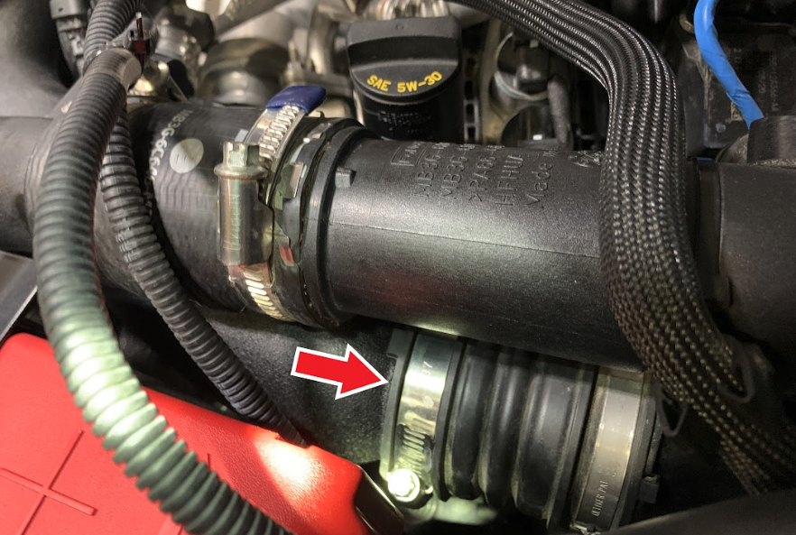
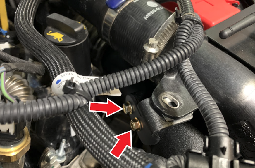
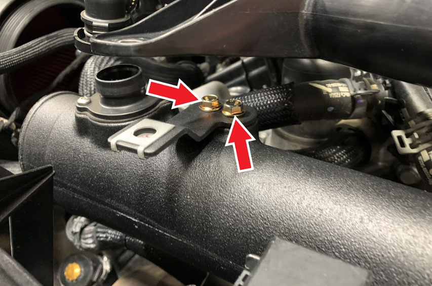
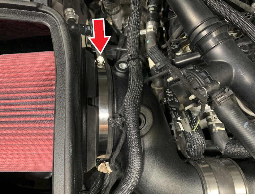
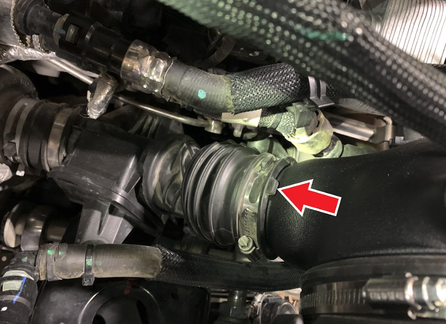
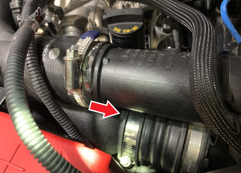
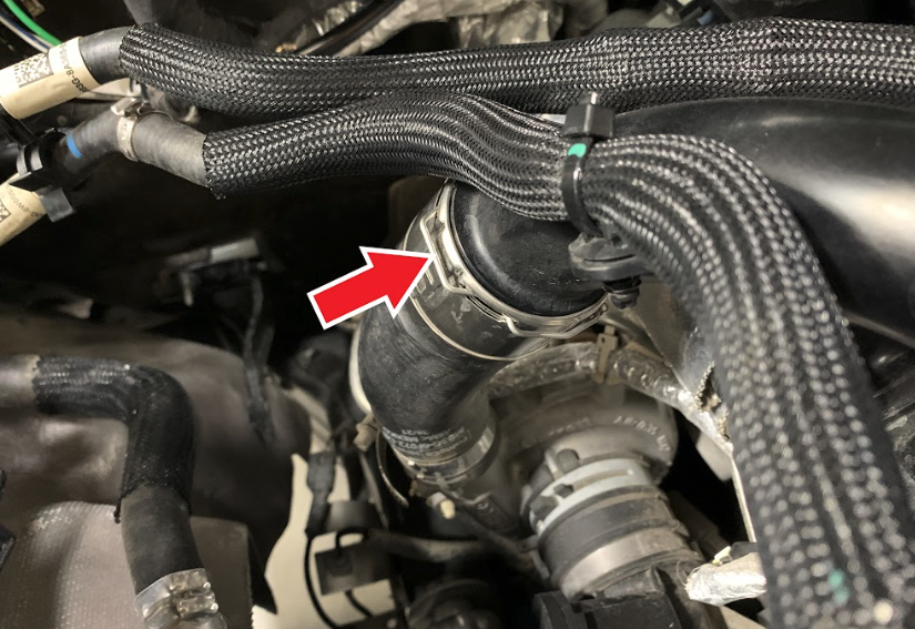
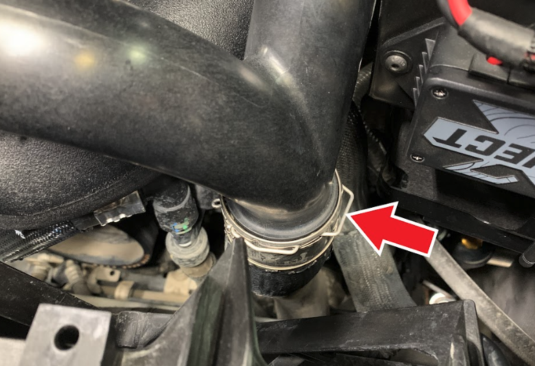
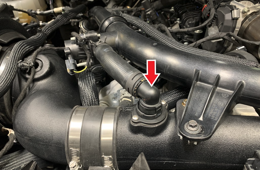
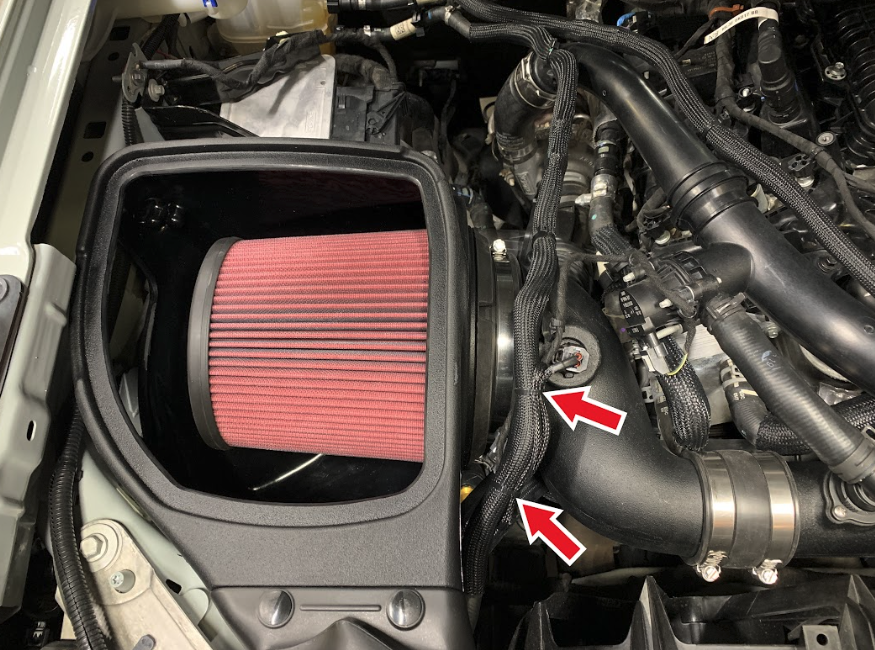
• Intake Tubes and Filter connections and Intake Box fasteners making sure they are tight.

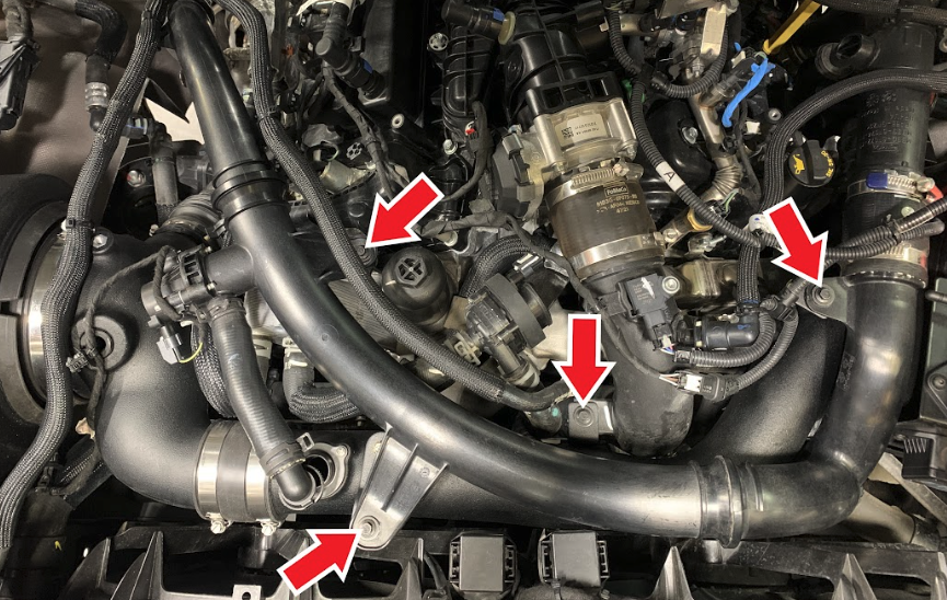
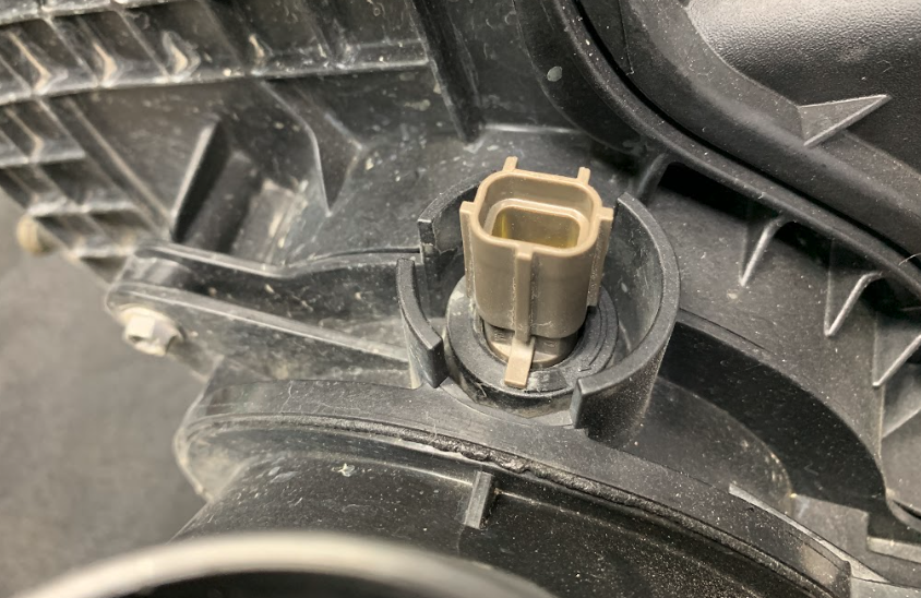
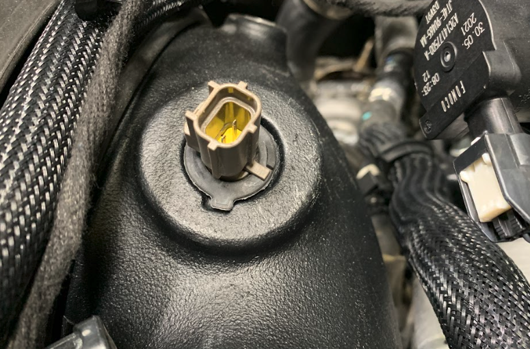
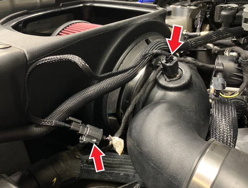
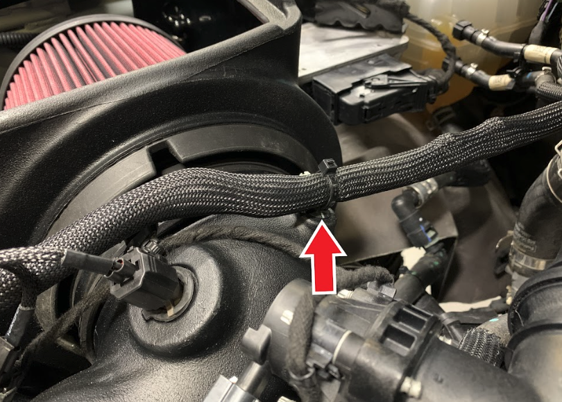
• All electrical connections and wire harnesses moved during the installation of the intake and make sure they are secure and away from any hot or moving components.

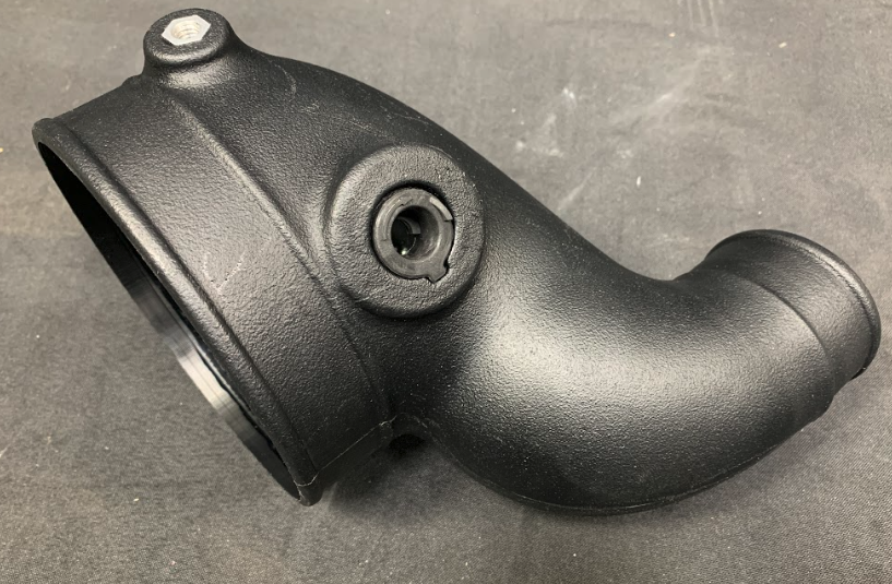
• Check for any signs of abrasion or wear and tear on the intake tube, box, filter, and electrical harnesses moved or near the intake and repair/replace as necessary.


Required Tools

7mm, 8mm, and 10mm, Socket and ¼” Drive Wrench

7mm Deep Socket

3” Socket Extension

6” Socket Extension or 3” + 3” Socket Extensions

3/4” Open/Box Combination Wrench

5/16” Nut Driver

Panel Popper

Phillips Screwdriver

Wire Cutters


Note: Approximate Install Time: 1 Hr

STEP 1

With the ignition switched off, make sure the vehicle is in Park and the parking brake set. Make sure the engine has cooled down.


CAUTION: The turbocharger compressor vanes can be damaged by small particles. When removing engine air intake system components, make sure no debris enter the system.

STEP 2

Pop out the stem and remove the push-in rivet securing the stock front inlet. Set the push-in rivet aside, it will be reused later.


Tools Required: Panel Popper

STEP 3

Remove the connector from the IAT sensor. Push down to release the locking tab and then pull the connector away from the sensor.

STEP 4

Remove the ribbed push-in retainer clips from the intake box. Use a panel popper to carefully remove the retainer clips.


Tools Required: Panel Popper

STEP 4 (IMAGE 2)

STEP 5

Loosen the hose clamp attached towards the front of the intake box.


Tools Required: 7mm Socket/Wrench, 3” extension

STEP 6

Remove hose from the intake box and position it aside.

STEP 7

Loosen the hose clamp attached towards the rear of the intake box.


Tools Required: 7mm Socket/Wrench, 3” extension

STEP 8

Remove hose from the intake box and position it aside.

Step 9

Remove the screw that mounts the rear corner of the intake box to the fender frame. Set the screw aside to be used later.


Tools Required: 10mm Socket/Wrench

STEP 10

Firmly but carefully rock and lift the intake box free from the lower grommets.Lift and remove the intake box from the vehicle.

STEP 11

Make sure the bottom box grommets stayed in the vehicle and did not get pulled out with the intake box.

STEP 12

Loosen and remove the (4) screws holding down the charge air pipe. Set the screws aside to be reused later.


Tools Required: 8mm Socket/Wrench, 3” extension

STEP 13A

Disengage the quick connect spring clip located on the passenger side of the charge air pipe

STEP 13B

Pull one end of the spring clip away from the quick connect and lock it into the open position.

STEP 13C

Pull the other end of the spring clip away from the quick connect and lock it into the open position.

STEP 13D

Remove the charge air pipe from the quick connect and set aside.

STEP 14A

Disengage the quick connect spring clip located on the driver side of the charge air pipe near the battery.

STEP 14B

Pull one end of the spring clip away from the quick connect and lock it into the open position.

STEP 14C

Pull the other end of the spring clip away from the quick connect and lock it into the open position.

STEP 14D

Remove the charge air pipe from the quick connect and set aside.

STEP 15

Squeeze the by-pass hose quick connect collar to release the locking tabs and remove the hose from the long intake tube. Set the by-pass hose aside.

STEP 16

Loosen the hose clamp of the coupler attached at the other end of the long intake tube located by the battery.


Tools Required: 7mm Socket/Wrench, 6” extension

STEP 17

Work the long intake tube back and forth to remove it from the coupler by the battery.

STEP 18A

Carefully lift the charge air pipes to give enough room to remove the long intake tube from the engine. Set aside the long intake tube for use later.

STEP 18 (IMAGE 2)

STEP 19

Install the Box Bracket (2) to the Intake Box (1) using two Screws (3). Tighten the Screws to secure the Bracket.


Tools Required: 10mm Socket/Wrench

STEP 20

Remove the shoulder bushing and grommet from the stock intake box and install them to the Box Bracket (2). Note the orientation of the grommet and bushing when installing them to the Box Bracket.

STEP 20 (IMAGE 2)

STEP 21

Install the Front Scoop (4) to the Intake Box (1). Use the Plastic Rivets (5) to secure the Scoop to the Intake Box. There are (4) holes in the Intake Box for the Scoop and each hole will have (2) Plastic Rivets that interlock to each other and sandwich the Scoop to the Intake Box.

STEP 22

Determine if you want to install the Box Plug (6) onto the Air Box (1). For optimal performance, we recommend that the intake be used without the Plug except in conditions of extreme heat. If the Box Plug is desired, simply press the Box Plug into the Box opening until it snaps fully into place.

STEP 23

Install the Intake Box (1) into the vehicle. Make sure that the box prongs are aligned with the factory grommets. Push down on the airbox to make sure that the prongs are completely seated.

STEP 23 (IMAGE 2)

STEP 24

Align the grommet hole in the Box Bracket (2) with the threaded hole in the fender frame and reuse the screw removed in Step 9 to fasten the Box Bracket to the fender frame. Tighten the screw.


Tools Required: 10mm Socket/Wrench

STEP 25

Reinstall the plastic rivet removed in Step 2 to secure the Front Scoop (4).

STEP 26

Install the Filter (7) into the Intake Box (1). Insert the Filter flange first through the top opening of the Box. Center the Filter flange with the round filter opening of the Box. Make sure that all around the tip of the tapered snap-in feature of the filter is inside the round filter opening before you use the filter flange to pull the filter until the tapered feature completely snaps around the outside of the round opening.

STEP 26 (IMAGE 2)

STEP 26 (IMAGE 3)

STEP 27

Install the Gasket (16) onto the Long Tube (15). Then place the Adapter (17) over the Gasket making sure the holes align with the Gasket and the threaded holes on the Tube. Use Screws (18) to fasten them tightly together.


Tools Required: Phillips Screwdriver

STEP 27 (IMAGE2)

STEP 28

Line up the stock tube with the Long Tube (15) and arrange the Brackets (19), (20) and (21) to their corresponding locations as shown. Transfer the stock clip nuts from the stock tube to Bracket (19) and Bracket (21). You can remove the stock clip nuts by sliding a flat screwdriver underneath them as shown.


Tools Required: Flat Screwdriver or Panel Popper

STEP 28 (IMAGE 2)

STEP 29

Install Bracket (20) to the Long Tube (15) with the Screws (3) and tighten all screws.


Tools Required: 10mm Socket/Wrench

STEP 30

Install the Long Tube (15) underneath the boost tubes. Lift up the boost tubes to give you more room to fully insert the Long Tube into the coupler by the driver’s side battery.

STEP 30 (IMAGE 2)

STEP 31

Install Bracket (21) to the Long Tube (15). Make sure the Bracket is underneath the boost tube mounting tab as shown. Use Screws (3) to tighten the Bracket to the Tube.


Tools Required: 10mm Socket/Wrench

STEP 32

Install Bracket (19) to the Long Tube (15). Make sure the Bracket is underneath the boost tube mounting tab as shown. Use Screws (3) to tighten the Bracket to the Tube.


Tools Required: 10mm Socket/Wrench

STEP 33

Install the IAT Sensor Grommet (12) to the Y Tube (11). Make sure the tab on the Grommet lines up with the notch in the Tube and the Grommet is fully seated in the Tube as shown.

STEP 34

Install the Coupler (13) to the Y Tube (11). Make the Coupler as flush as possible to the Tube for an easier install. Loosely attach the Hose Clamps (14) around the Coupler as shown.

STEP 35

Install the Y Tube (11) into the Filter (7) flange making sure the Y Tube is underneath the coolant line and bypass valve wire harness as shown. Then push back the stock flexible coupler to give you room to insert the flexible coupler onto the small end of the Y Tube.

STEP 35 (IMAGE 2)

STEP 36

Slide the Coupler (13) over the Long Tube (15) so that the Y Tube (11) and Long Tube are fully inserted into the Coupler as shown. Make sure both Hose Clamps (14) are positioned within the Clamp groove and tighten the Hose Clamps.


Tools Required: 5/16” Nut Driver

STEP 37

Slide the Hose Clamp (8) over the Filter (7) flange and position within the clamp groove as shown. Then make sure the Y Tube is fully inserted Into the Filter flange and tighten the Clamp.


Tools Required: 5/16” Nut Driver

STEP 38

Make sure the Y Tube (11) is fully inserted into the flex coupler. A bead on the Y Tube will indicate where the end of the flex coupler should be. There is also a cut out on the bead to indicate where the tab on the flex coupler should also be. Once the flex coupler is properly positioned, tighten the hose clamp as shown.


Tools Required: 7mm Socket/Wrench, 3” extension

STEP 39

Make sure the Long Tube (15) is fully inserted into the flex coupler by the driver’s side battery. A bead on the Long Tube will indicate where the end of the flex coupler should be. There is also a cut out on the bead to indicate where the tab on the flex coupler should also be. Once the flex coupler is properly positioned, tighten the hose clamp as shown.


Tools Required: 7mm Socket/Wrench, 6” extension or 3”+3” extension

STEP 40

Engage the quick connect spring clip located on the passenger side of the charge air pipe and insert the pipe back into the quick connect fitting until it clicks and locks into place.

STEP 41

Engage the quick connect spring clip located on the driver side of the charge air pipe and insert the pipe back into the quick connect fitting until it clicks and locks into place.

STEP 42

Hand tighten the (4) screws removed in Step 12 to secure the charge air pipe. Then fully tighten all screws.


Tools Required: 8mm Socket/Wrench, 3” extension

STEP 43

Connect the by-pass hose to the Long Tube (15). Push in the quick connect until it locks into place on the Adapter (17).

STEP 44

Remove the IAT sensor from the stock intake. Lean the IAT Sensor back as you rotate it counterclockwise so that the tab on the sensor goes over the locking ramp. Once the sensor tab is passed the locking ramp it can be pulled out and removed.

STEP 45

Install the IAT sensor into the IAT Sensor Grommet (12). First line up the sensor tab so that it is between the arrowhead and locking ramp on the Grommet. Then insert the sensor so that the tab is touching the Grommet. Finally twist the IAT sensor so that the tab goes over the ramp on the Grommet. A properly installed IAT sensor should look like the picture shown.

STEP 46

Connect the IAT Extension Harness (22) to the IAT sensor and wire harness.

STEP 47

Insert the ribbed push-in retainer clip on the coolant line into the threaded insert on the Y Tube (11). If the original ribbed push-in retainer clip is broken, you can replace it with the provided Push In Cable Tie (24).

STEP 48

Use Cable Ties (23) to neatly bundle the IAT Harness Extension (22) together with the coolant line so that it is secured away from any hot or moving components and also not rubbing against any components. Trim the excess Cable Tie with wire cutters.


Tools required: Wire Cutters

STEP 49

Remove the protective covering over the Clear Lid (10) and then insert the Lid into the Lid Seal (9). Then install the Lid Seal with Lid onto the top opening of the Box. Start with one corner of the Box and work your way around until the Lid Seal with Lid is fully snapped into the Box opening.

STEP 50

Inspect your installation, make sure the kit is properly positioned and all fasteners and hose clamps are secured. Keep all stock parts in case you would ever need to reinstall the stock intake assembly. If you are an installer, give the owner the QR code for the Installation Instructions so that he/she is aware of the "Periodically Check the Following" procedures given in the beginning of the Instructions. The Installation is now complete.