Install Instructions for 75-5137-1

Before You Start

Note:


This intake kit may not fit with the following Aftermarket Parts installed:

Body Lift or Lowering Kit

Custom Hood


Please read the entire product guide before proceeding. Ensure all parts are present. If you are missing any of the components, call our customer support at (909) 947-0015. Do not work on your vehicle while the engine is hot. Make sure the engine is turned off and the vehicle is in Park or the Parking Brake is set.

Required Tools

7mm, 10mm, 13mm Wrench, 5/16” Nut Driver or Flat Blade Screwdriver, Pin Removal Tool or Flat Blade Screwdriver, T15, T20 Torx Bit,  Phillips Screwdriver, 5/32” or 4mm Allen Wrench, 1 Pair of Pliers or similar tool, Topside Engine Creeper recommended.

Note: Approximate Install Time: 2 Hr 00 Mins.

STEP 1

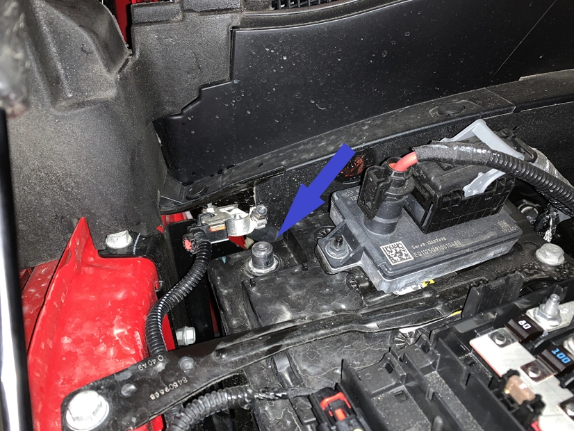
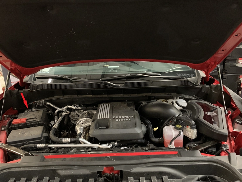
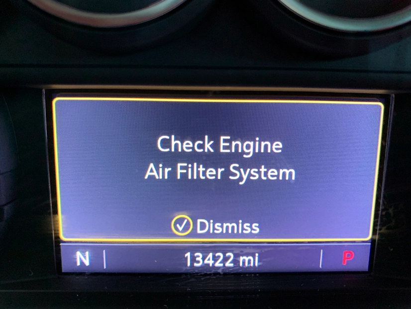
Disconnect Battery. Disconnect the negative battery cable by loosening the terminal clamp and removing it from the battery post. Note: Failure to disconnect the battery for a minimum of 2 hours may cause the CEL to illuminate upon completion of the installation and subsequent operation. Do not skip this step!

Tool Needed: 10mm Wrench or Socket.

STEP 2

Remove hood latch lever.

Tool Needed: T15 torx bit.

STEP 3

Remove the push clips holding down the large plastic air diverter. Remove the large plastic air diverter and set aside.

Tool Needed: Panel removal tool or similar.

STEP 4

Disconnect and remove the support brace near the stock air inlet tube.

Tool Needed: 13mm Wrench or Socket.

STEP 5

Remove the push clip holding the top of the air inlet tube in place, and set the clip aside, separate from the other clips, as this one is unique.

Tool Needed: Panel removal tool or similar.

STEP 6

Disconnect the radiator support brace spanning from the core support to frame.

Tool Needed: 13mm Wrench or Socket.

STEP 7

Remove the bolt holding down the front coolant overflow tube.

Tool Needed: 10mm Wrench or Socket.

STEP 8

Remove the bolt holding down the fuse box bracket, and push the fuse box as far forward and out of the way as possible.

Tool Needed: 10mm Wrench or Socket.

STEP 9

Pull the stock air inlet tube up enough that it is no longer connected to the stock airbox, it is not necessary to remove the tube to install the S&B Filters Cold Air Intake

STEP 10

Carefully disconnect the large wire harness at the front of the air intake. The snap feature is designed to release under sufficient upward force, however, pulling upward while tilting the harness toward the rear of the vehicle will help disconnect the harness.

STEP 11

Disconnect the push clips (wrapped into the harness) from the stock air intake, there should be three, two toward the front of the vehicle and one toward the engine.

Tool Needed: Panel removal tool or similar.

STEP 12

Disconnect the MAF Harness. Pull back on the red tab to unlock the connector. Press down on the black tab directly under the red tab and pull rearward to disconnect the connector.

STEP 13

Loosen the hose clamp on either end of the stock flexible coupler, the coupler can now be removed from between the stock intake tube and the stock air box.


Tool Needed: 7mm nut driver or Flat Blade Screwdriver.

STEP 14

Loosen the nut with a captive washer holding down the stock air box. Set aside the nut for reuse.


Tool Needed: 10mm wrench or socket.

STEP 15

Remove the stock air box by lifting the front high enough to clear the stud, and pulling the airbox forward, sliding the rear facing prongs out of the bracket.

CONFIGURATION

STOP. AT THIS POINT YOU NEED TO DECIDE WHICH CONFIGURATION YOU WANT TO INSTALL. IF YOU WANT TO INSTALL THE S&B INTAKE SYSTEM TO THE TURBO, PROCEED TO STEP 16, IF YOU WANT TO INSTALL TO THE STOCK INTAKE TUBE SKIP AHEAD TO STEP 24.

STEP 16

Remove the engine cover by unscrewing the hold down bolt. Unscrew the oil fill cap. Lift the front of the cover and pull the cover toward the front of the vehicle. Be sure to replace the oil fill cap.

Tool Needed: 10mm Wrench or Socket.


STEP 17

Remove the bolt holding down the rear coolant reservoir. Let the reservoir rest where the stock air box was formerly located. If you wish to disconnect either of the overflow lines, be sure to unscrew the cap to relieve the pressure in the reservoir.

Tool Needed: 10mm Wrench or Socket.

STEP 18

Loosen the hose clamp closest to the turbo inlet on the stock tube. The access to this hose clamp is very limited, caution and patience are required.

Tool Needed: 7mm socket or Nut Driver, or Flat Blade Screwdriver.

STEP 18B

STEP 19

Lift upward on the intake tube, until you feel it release. There is a mounting point with a grommet molded into the intake tube, this must be dislodged before the tube can be removed. Once the tube is free, the easiest way to remove it is by pulling it toward the driver’s side and pulling it through the area where the coolant reservoir was.

STEP 20

Find the long S&B Intake tube (3) and the mounting bracket hardware kit (HP1725-00). Attach the small grommet (26) to the bracket (25) and the bracket to the tube with the ¼ x 20 Button Head Cap Screws (17).

Tool Needed: 5/32” or 4mm Hex Key.

STEP 21

Attach the Step Coupler (7) to the Long Intake Tube using the #56 hose clamp (21). Snug the #48 hose clamp (20) on the small end of the coupler, but do not fully tighten.

STEP 22

Feed the long tube through the engine bay and slide the coupler onto turbo inlet. It is possible to feel the mounting ball for the bracket, shown in the photo, and with the tube on the turbo inlet the alignment should be close. Line the ball and bracket up and push down on the tube until it seats. Tighten the hose clamp on the turbo inlet.

Tool Needed: 7mm nut driver or Flat Blade Screwdriver.

STEP 23

Reinstall rear coolant reservoir and mounting bolt.

Tool Needed: 10mm socket or wrench

STEP 24

Find the S&B Air Intake Box (1) and the Silicone Inlet Seal (5).

Install the Inlet Seal onto the Air Box.

STEP 25

Attach the Harness Bracket (6) onto the airbox with the ¼ x 20 Button Head Cap Screw (17).

Tool Needed: 5/32” or 4mm Hex Key.

STEP 26

Install the Panel Grommet (16) into the Air Box Mounting Bracket (23). Install the Machined Aluminum Shoulder Washer (15) into the Panel Grommet (16). Install the Air Box Mounting Bracket (23) with the ¼ x 20 Button Head Cap Screws (17).

Tool Needed: 5/32” or 4mm Hex Key.

STEP 27

If desired, install the Silicone Box Plug (12) into the side of the airbox. The plug is designed to be able to be inserted from either the interior or exterior of the box; install according to preference.

STEP 27B

STEP 28

Install the Mounting Prong Grommets (18) onto the rear prongs on the Air Box.

STEP 29

Install the Airbox into the vehicle, sliding the prongs into their holes and lowering the box onto the stud. Loosely Reinstall the nut with a captive washer onto the stud.

STEP 30

Separate the fuse box from the fuse box bracket by pressing the tab, and pulling the two apart.

STEP 31

Reinstall the fuse box bracket. Ensure the fuse box is near, but not attached to the bracket.

Tool Needed: 10mm wrench.

STEP 32

Reinstall the Radiator core support bracket. Ensure the fuse box is beneath the bracket, in its stock area, before tightening the bracket.

Tool Needed: 13mm Wrench or Socket.

STEP 33

Insert the stock air inlet tube into the Inlet Seal on the S&B Air Box. The stop on the stock air inlet tube should be touching the seal when fully inserted. It may be helpful to guide the tube with one hand inside the air box.

STEP 34

Reattach the unique push clip for the air inlet tube and reinstall the support bracket. 

Tool Needed: 13mm Wrench or Socket.

STEP 35

Tighten down the nut with a captive washer to secure the airbox.

Tool Needed: 10mm wrench or socket.

STEP 36

Re-attach fuse box to fuse box bracket.

STEP 37

Attach the large, forward wire harness to the Harness Bracket.

STEP 38

Insert the push clips into the small holes in the S&B Air Box.

STEP 39

Reinstall the bolt holding down the front coolant reservoir.

Tool Needed 10mm socket or wrench.

STEP 40

Reinstall the large plastic air diverter and hood latch lever.

Tool Needed: T15 torx bit.

STEP 41

Attach the Push In Cable Tie (29) into the upper hole in the back side of the airbox, and loop it back into itself, leaving it loose. This tie will be tightened at the end of the installation.

STEP 42

Attach the Straight Coupler (24) to the Long S&B Intake Tube using the supplied #72 Hose Clamp (19) and tighten with the coupler against the stop bead. If the Long Tube installation was skipped, attach to the stock tube.

Tool Needed: 5/16 nut driver or similar.

STEP 43

Find the S&B Air Filter (4) and snap the filter into the airbox. The installation is easiest when the snap is chased around the perimeter of the filter base, starting with the lowest point of the filter. Attach the #88 Hose Clamp (22) if not already attached.d

STEP 44

Remove the MAF sensor from the stock air box lid.

Tool Needed: T20 torx bit.

STEP 45

Find the Short S&B Intake Tube (2) and HP1407-00. Install the MAF Sensor into the Short S&B Intake Tube using the MAF Pad (9), MAF Gasket (10), and supplied screws (11). Take care that the MAF pad and sensor are oriented correctly on the MAF boss on the tube, as shown.


Tool Needed: Philips Head Screwdriver

STEP 46

Insert the Short S&B Intake Tube into the Straight Coupler, then insert the tube into the Filter flange. Tighten both hose clamps.

STEP 47

Attach the MAF Harness Extension Cable (8) to the MAF sensor.

STEP 48

Feed the MAF Harness Extension Cable through the cable tie installed in Step 41 to keep it away from hot surfaces or moving parts.

STEP 49

Connect the MAF Harness Extension Cable to the stock MAF Harness and tighten the Push In Cable Tie.

STEP 50

Zip tie the stock MAF harness to the large wire harness in front.

STEP 51

Reinstall the engine cover.

Tool needed: 10mm socket.

STEP 52

Install the plug (27) into the socket access hole on the airbox.

STEP 53

Find the S&B clear lid (14). Remove the film.

STEP 54

Install the lid into the lid seal (13).

STEP 55

Install the lid and lid seal into the airbox starting from the tight corners and curved edge, working to the straight side.

STEP 56

Reconnect the Battery connections. Inspect your installation, ensure the kit is properly positioned and all fasteners are secure. The installation is now complete.

STEP 57

To prevent the following message from displaying, the Air Filter Life system will need to be disabled.

STEP 58

Navigate to the Options section of the Driver Information Center, and select the Info Page Options.

STEP 59

Ensure that the Air Filter Life has a green check mark next to it.

STEP 60

Navigate to the Info section of the Driver Information Center, and scroll down to the Air Filter Life section. Press the wheel in to select the Menu for the Air Filter Life, and select Disable.

STEP 61

The screen should now display “Disabled”, as shown. Please verify the screen still shows disabled after the battery disconnect has been completed. If not, please repeat the process.