Install Instructions for 75-5135

Before You Start

  • Please read the entire product guide before proceeding. 
  • Ensure all parts are present.
  • If you are missing any of the components, call our customer support at (909) 947-0015.
  • Do not work on your vehicle while the engine is hot.
  • Make sure the engine is turned off and the vehicle is in Park or the Parking Brake is set.
  • Note: This intake kit may not fit with the following Aftermarket Parts installed: Body Lift or Lowering Kit, Custom Hood, Throttle Body Spacer / Upgrade


PERIODICALLY CHECK THE FOLLOWING:

⦁ Intake Tube and Filter connections, Intake Box fasteners, and Battery Tray fasteners, making sure they are tight.

⦁ At every engine oil change service, check all electrical connections and wire harnesses moved during the installation of the intake and make sure they are secure and away from any hot or moving engine components.

⦁ At every engine oil change service, check for any signs of abrasion or wear and tear on the intake tube, box, filter, and electrical harnesses moved or near the intake and repair/replace as necessary.

⦁ Service and check the condition of your Foam Filter every time you service your air filter. Wash it with water or gently blow it off with compressed air. If it can’t be cleaned with water or compressed air, or it is torn or damaged, please replace the foam filter. HP1473-00 is the replacement foam kit that includes (1) Foam Filter, (1) Foam Retainer, and (3) Screws.

Required Tools

  • 7mm, 8mm, 10mm (Deep), 13mm Wrench/Socket
  • 5/16” Nut Driver or Flat Blade Screwdriver
  • Phillips Screwdriver
  • Panel Popper
  • Heat Gun
  • T20 Torx
  • Wire Cutters

STEP 1

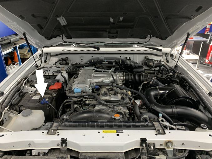
With the ignition switched off and the parking brake set, Disconnect the negative battery cables on both batteries and positive battery cable on the passenger side only.

Tools Required: Socket Wrench, 8mm Socket

IMPORTANT: Failure to disconnect the battery may cause the CEL to illuminate upon completion of the installation and subsequent operation. Do not skip this step!

STEP 2

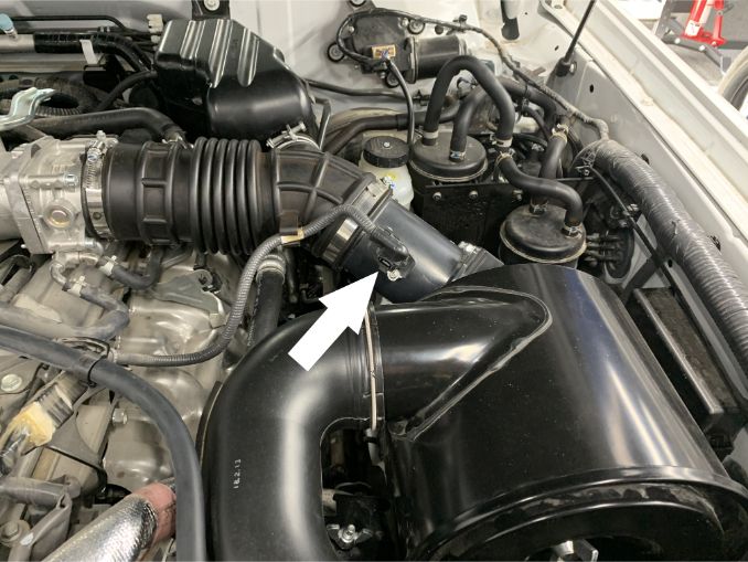
Push down on the black tab and pull out to remove the MAF harness connector from the MAF sensor.

STEP 3

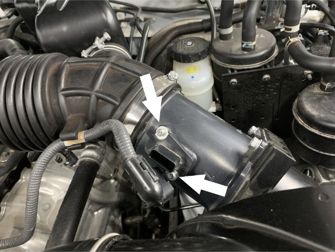
Remove the MAF sensor from the stock intake by unscrewing the two attachment screws.

Tools Required: T20 Torx

STEP 4

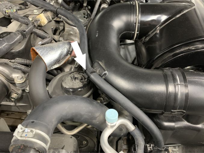
Unclip the engine hose from the 180 intake elbow and move it to the side so that you have room to remove the elbow from the vehicle. 


STEP 5

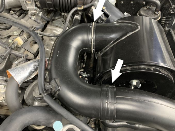
Remove the 180 degree elbow from the fender mounted intake tube by sliding the locking collars out of their grooves and pulling the elbow toward the engine.


STEP 6

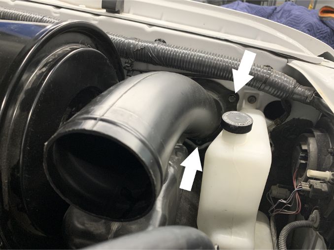
Remove the remaining piece of the fender mounted intake tube by removing the two screws securing it to the fender wall. Then pull the tube toward the engine to unseat it’s locking clip from the fender.

Tools Required: 10mm socket, ¼” socket wrench, ¼” socket extension


STEP 7

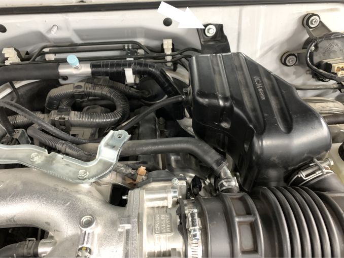
Remove the two screws securing the stock intake box.

Tools Required: 10mm socket, ¼” socket wrench

STEP 8

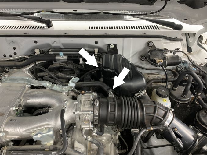
Remove the vent hose connected to the intake tube reservoir and the vent hose connected intake tube by loosening the clamp. Gently pull out the metal elbow from the vent hose as we will not be using it for the install of your new S&B cold air intake.

Tools Required: Needle Nose Pliers


STEP 9

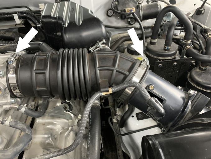
Loosen the two hose clamps connecting the intake tube to the throttle body and airbox. Then remove the intake tube from the vehicle, along with the still connected reservoir.

Tools Required: 8mm socket, ¼” socket wrench


STEP 10

Unscrew the two wingnuts connecting the airbox to it’s support brackets and remove the airbox from the vehicle.


STEP 11

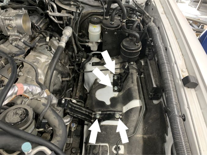
Remove the two airbox support brackets from the vehicle by taking out the 4 indicated screws.

Tools Required: 10mm socket, ¼” socket wrench


STEP 12

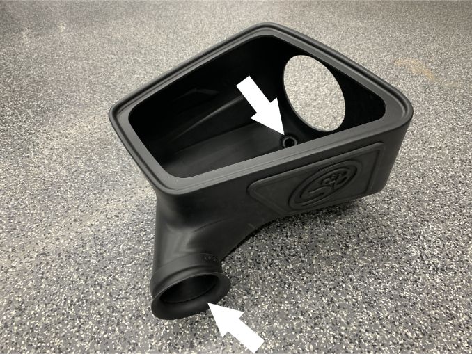
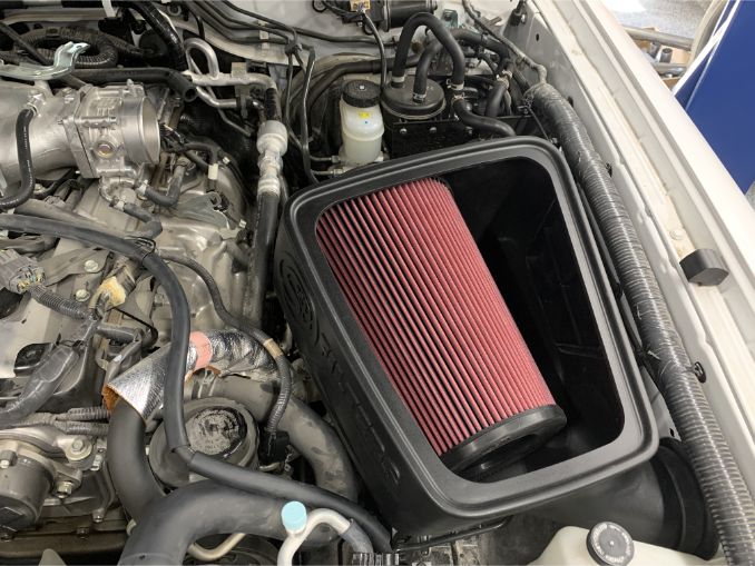
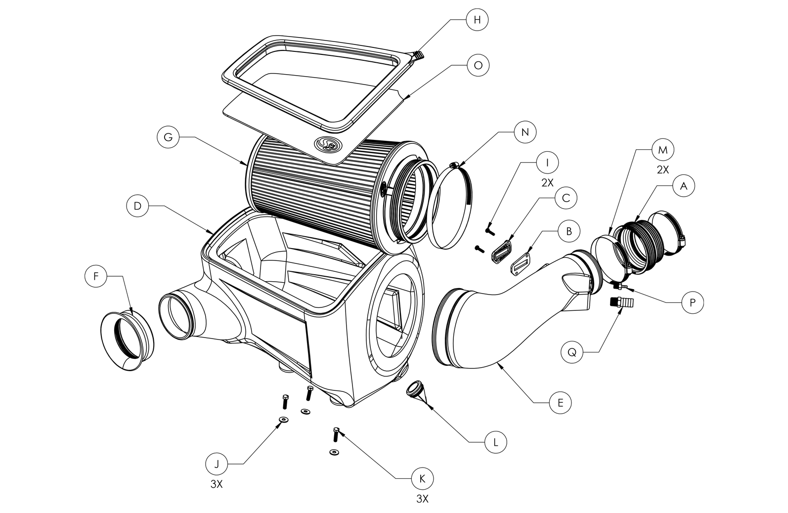
Now that the stock air intake system has been completely removed from the vehicle, begin assembling the S&B cold air intake system outside of the vehicle by installing the duck bill valve and fender seal onto the airbox.


STEP 13

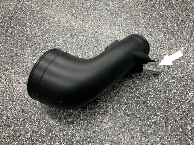
Prepare the S&B intake tube for installation by threading the provided barbed fittings into their respective holes on the tube.


STEP 14

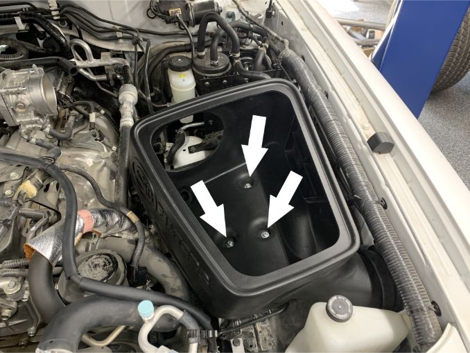
Place the assembled airbox into the vehicle and line up the mounting holes to the holes originally used to mount the stock airbox support brackets. Attach the airbox to the vehicle using the provided screws and washers. Do not tighten the screws all the way so that the airbox retains some side to side play.


STEP 15

Verify that the fender seal is lined up with the fender opening found on the side of the vehicle. When it has been confirmed that everything lines up properly, complete the tightening down of the airbox mounting screws.


STEP 16

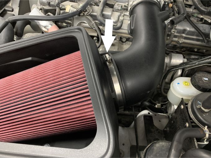
Install the filter into the airbox by placing it into the opening on the top of the airbox and pushing it toward the back of the vehicle so that the filter flange slips through and snaps into the hole found there. Verify that the filter is completely snapped into the airbox and that it is securely in place. Place the #104 hose clamp around the filter flange, and loosely tighten it so that it does not fall off.

STEP 17

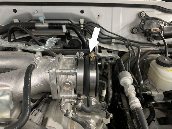
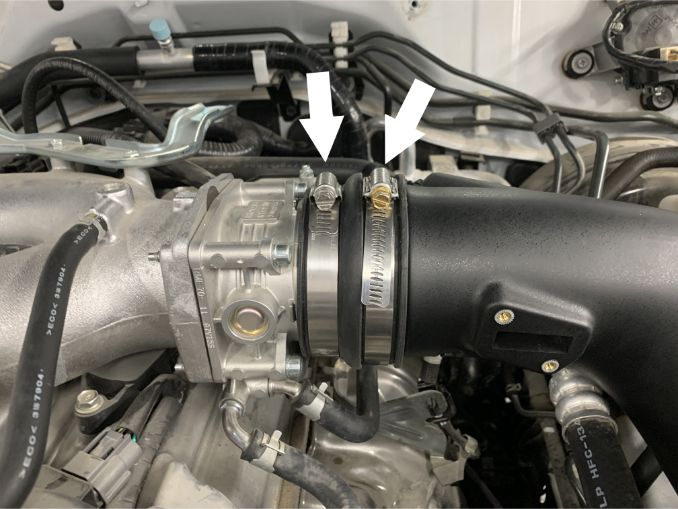
Place the provided coupler around the throttle body so that the end with the smaller diameter is facing the engine. Slide the coupler as far towards the engine as possible to make room for the installation of the intake tube. Loosely tighten the two smaller #56 hose clamps around each end of the coupler.


STEP 18

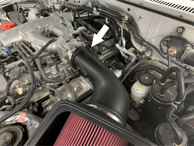
Install the intake tube into the vehicle by inserting the large end of the tube into the filter flange so that the rest of the tube is above the throttle body. When the large end is in place, rotate the tube so that the smaller end lines up with the opening of the throttle body.


STEP 19

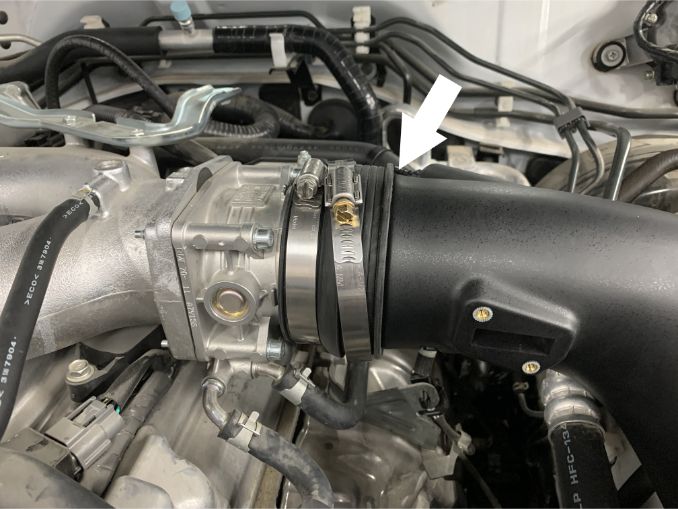
When the small end of the tube is in place, slide the large end of the coupler from step 16 over the end of the intake tube until it reaches the depth stop.


STEP 20

Tighten the hose clamps around both the throttle body and small end of the intake tube.

STEP 21

Ensuring that the intake tube is fully inserted in the filter flange, tighten the #104 hose clamp around the flange to secure the tube in place.


STEP 22

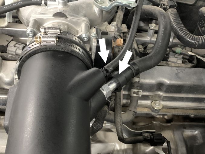
Attach the vacuum and vent hoses to the S&B intake tube by pressing them both onto their respective barbed fittings. Move the previously removed hose clamp over the area where the large vent hose engages with the fitting to secure it in place.

Tools Required: Needle Nose Pliers


STEP 23

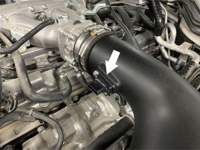
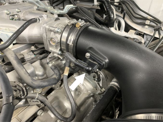
Attach the MAF sensor to the S&B intake tube using the provided MAF gasket, MAF adapter pad philips head screws. The MAF gasket should be contacting the tube with the adapter, pad followed by the MAF sensor, sitting on top of it.

STEP 24

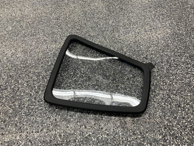
Stretch the provided lid seal around the S&B logo lid, ensuring that the cutout on the lid aligns with the pull tab on the lid seal.

STEP 25

Install the lid onto the top of the box by pushing down on all edges so that the lid seal firmly snaps into the ridges on the top of the box. Verify that the lid seal has completely snapped into place.

STEP 26

Connect the MAF sensor harness to the MAF sensor by pushing down and in on the red locking clip.

STEP 27

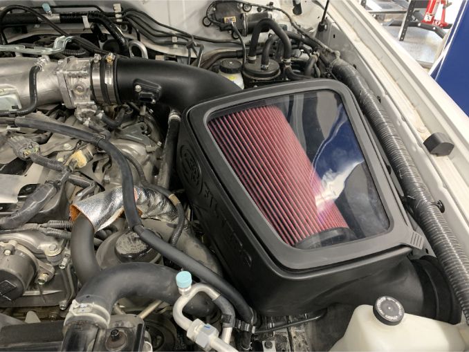
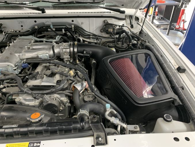
The installation of the S&B cold air intake is now complete. Take a moment to verify that everything is installed correctly and that all hose clamps and connections are not loose.