Attention: Before You Begin
This fuel tank is not compatible if your vehicle has an X-shaped cross member or V-shaped cross member between the frame and behind the transfer case.
*The cross member seen will be the one referenced in Step 15.
This fuel tank is not compatible if your vehicle has an X-shaped cross member or V-shaped cross member between the frame and behind the transfer case.
*The cross member seen will be the one referenced in Step 15.
Using a 8mm socket, loosen the hose clamps on the filler tube and vent tube.
Using a 10mm socket, uninstall the OE fuel tank skid plate by removing the 8 bolts. There are 2 bolts on each corner of the skid plate. Before removing the final bolts, place a jack or have a buddy help you catch the skid plate so it doesn't fall.

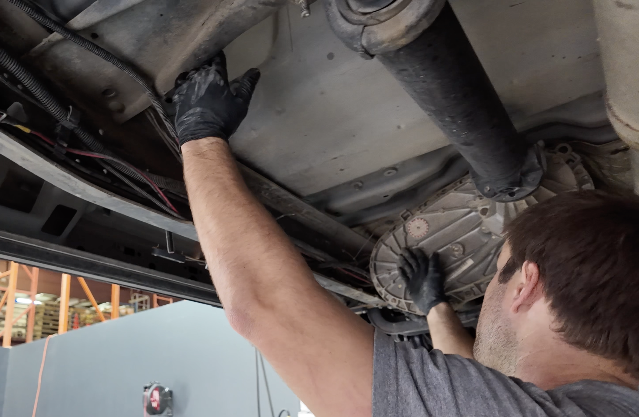
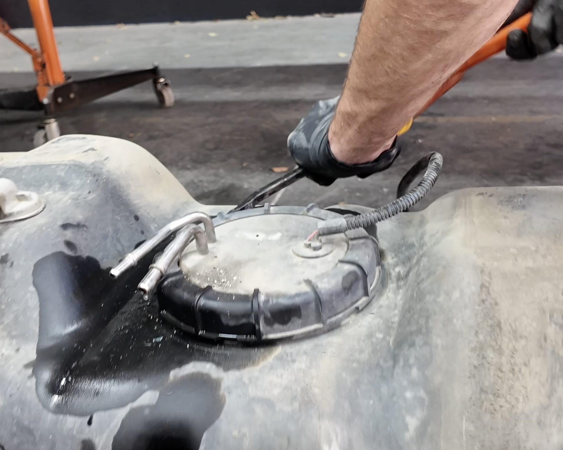
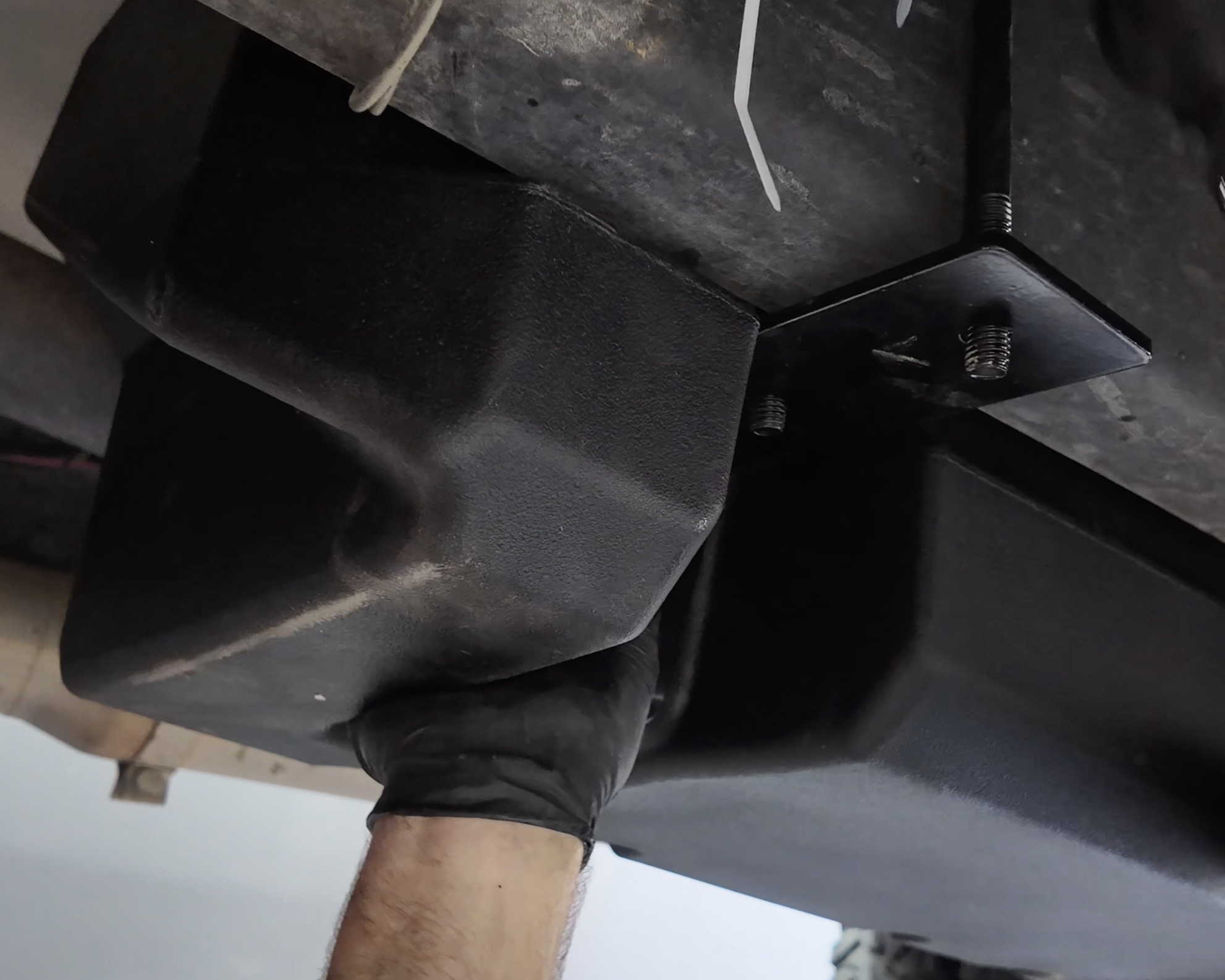
In order to disconnect the fuel sending unit, you're going to need to drop the tank a few inches. To do this, we recommend placing a jack under the tanks (as seen in this image) while you remove the hangars holding the fuel tank.
*Ensure that you don't place the jack below the sending unit (yellow arrow) as this will break the sending unit within the fuel tank.
.png?v=1765910436609)
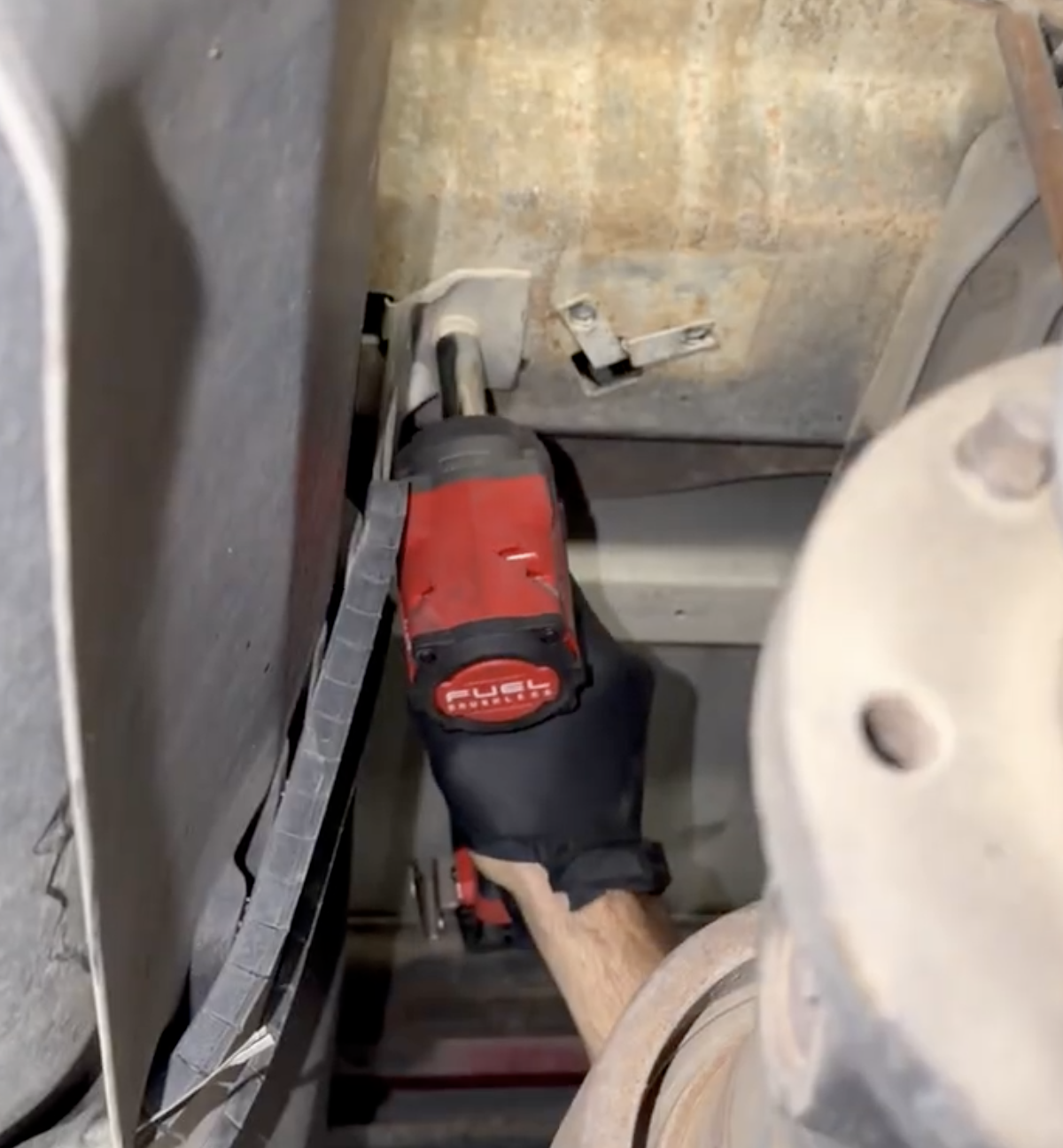
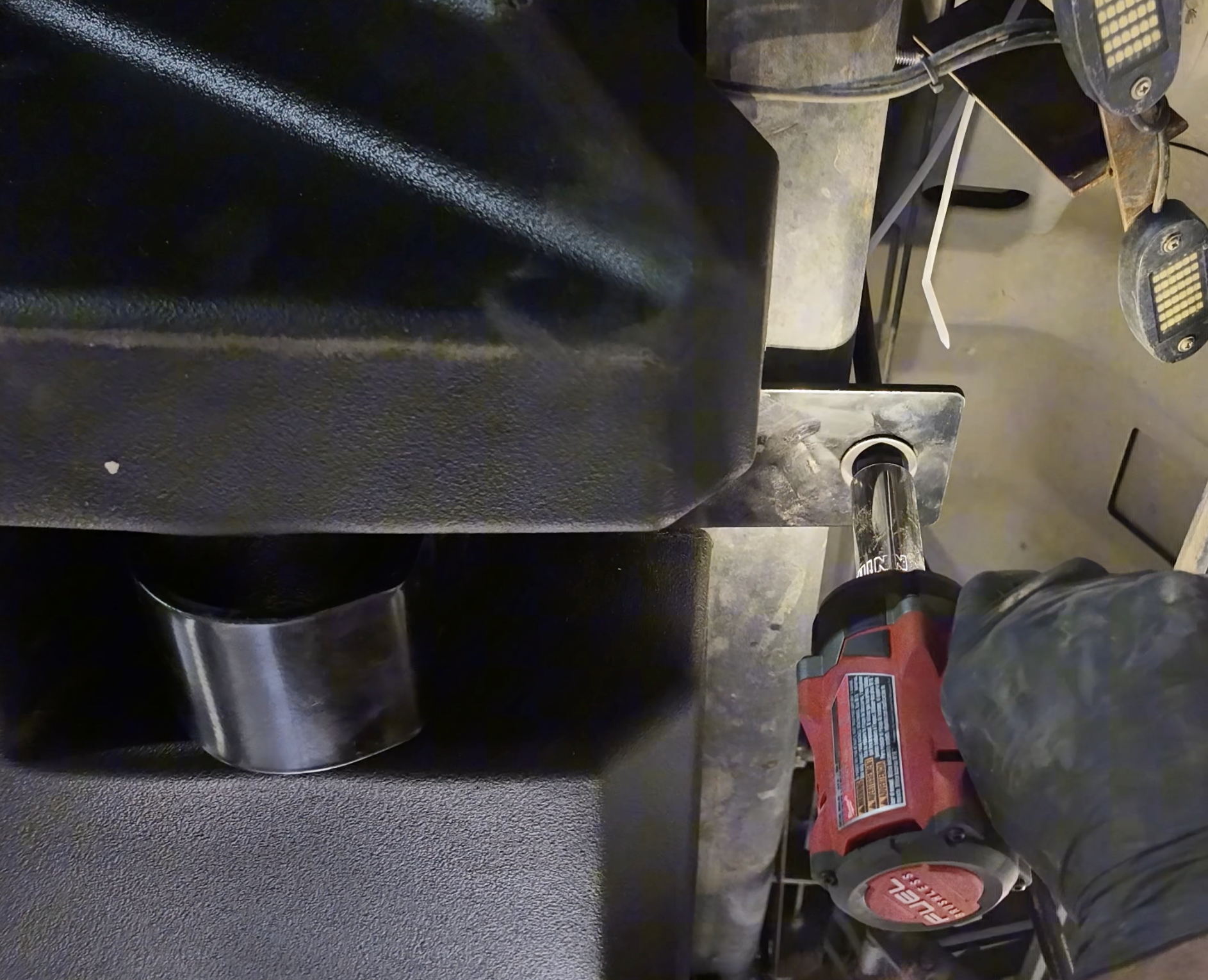
Using a 13mm socket, remove the 4 bolts holding the fuel tank straps to the vehicle.
*Make sure you keep the OEM bolts as you will re-use them in a later step.
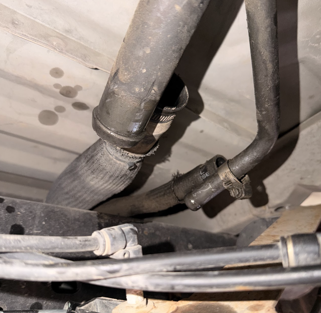
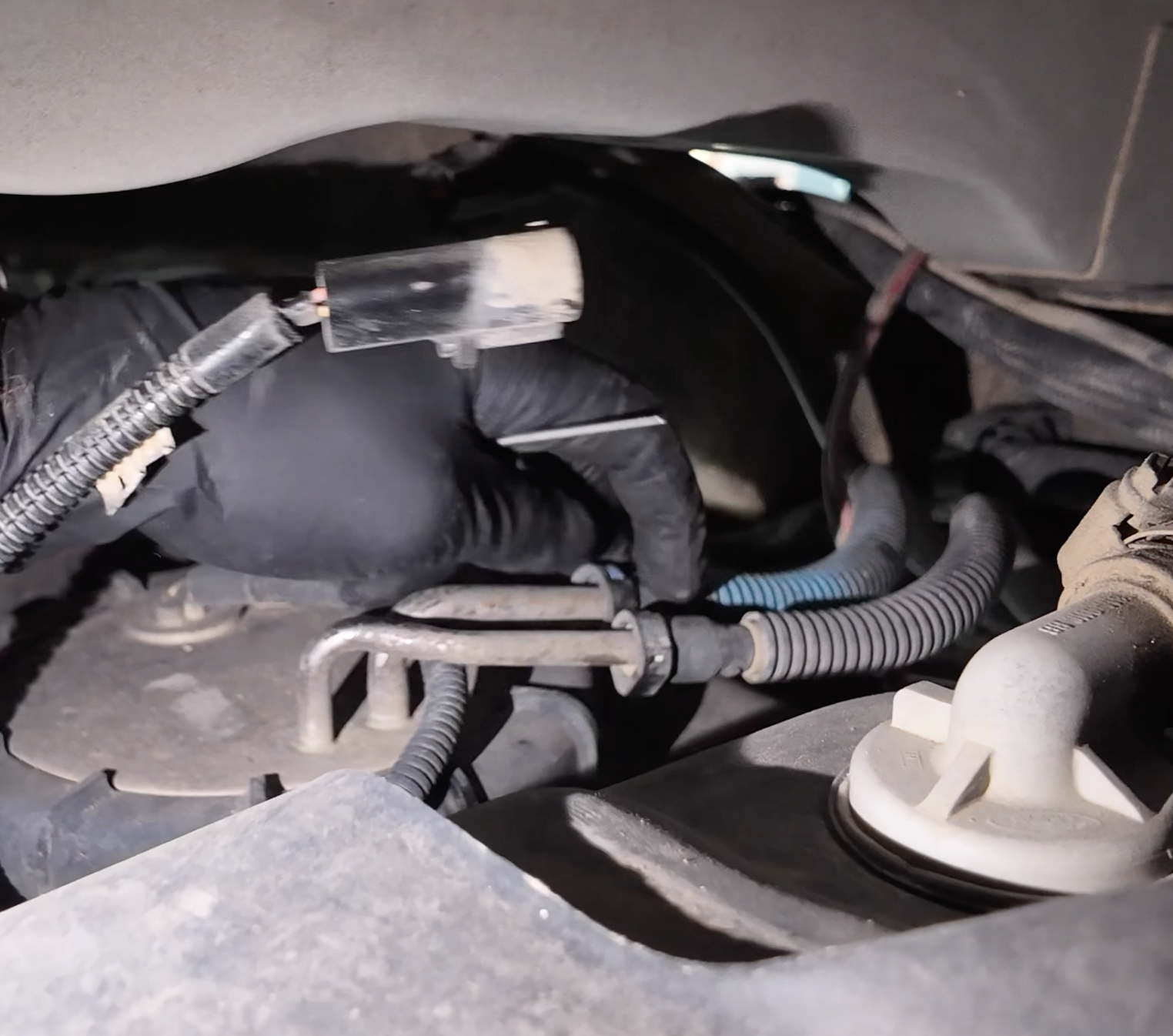
Drop the tank by a few inches to gain access to the 2 fuel lines (green arrows) and electrical connector (blue arrow) located at the top of the tank where the sending unit is.
.png?v=1765913539328)
Disconnect the electrical connector located above the sending unit.
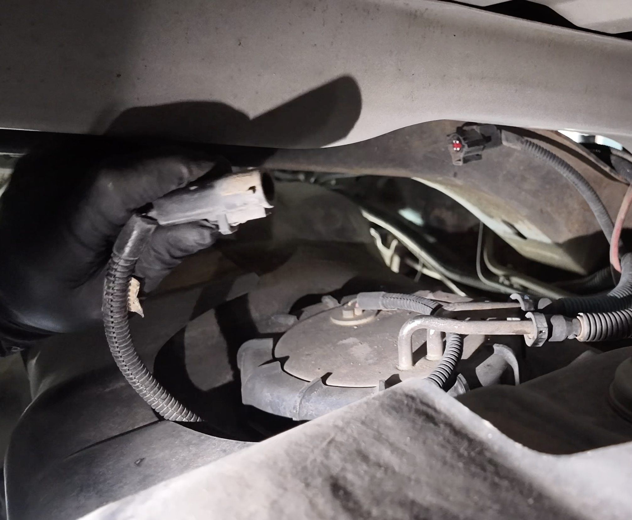
Disconnect the 2 fuel lines located at the top of the fuel sending unit by pushing the button on each of the connectors while simultaneously pushing them off the ports.
Now, go ahead and drop the fuel tank.
Using an 8mm, loosen the hose clamp on the filler tube port and the vent tube.
.png?v=1765915104591)
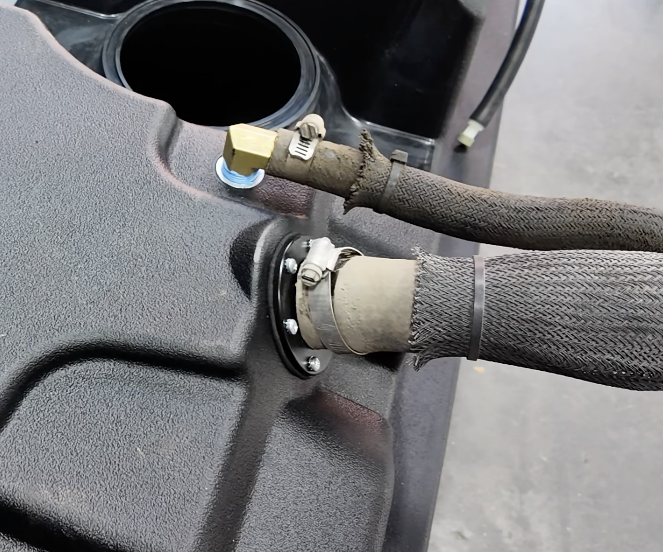
Connect the filler and vent tube to the S&B fuel tank. Then tighten down both hose clamps using an 8mm socket.
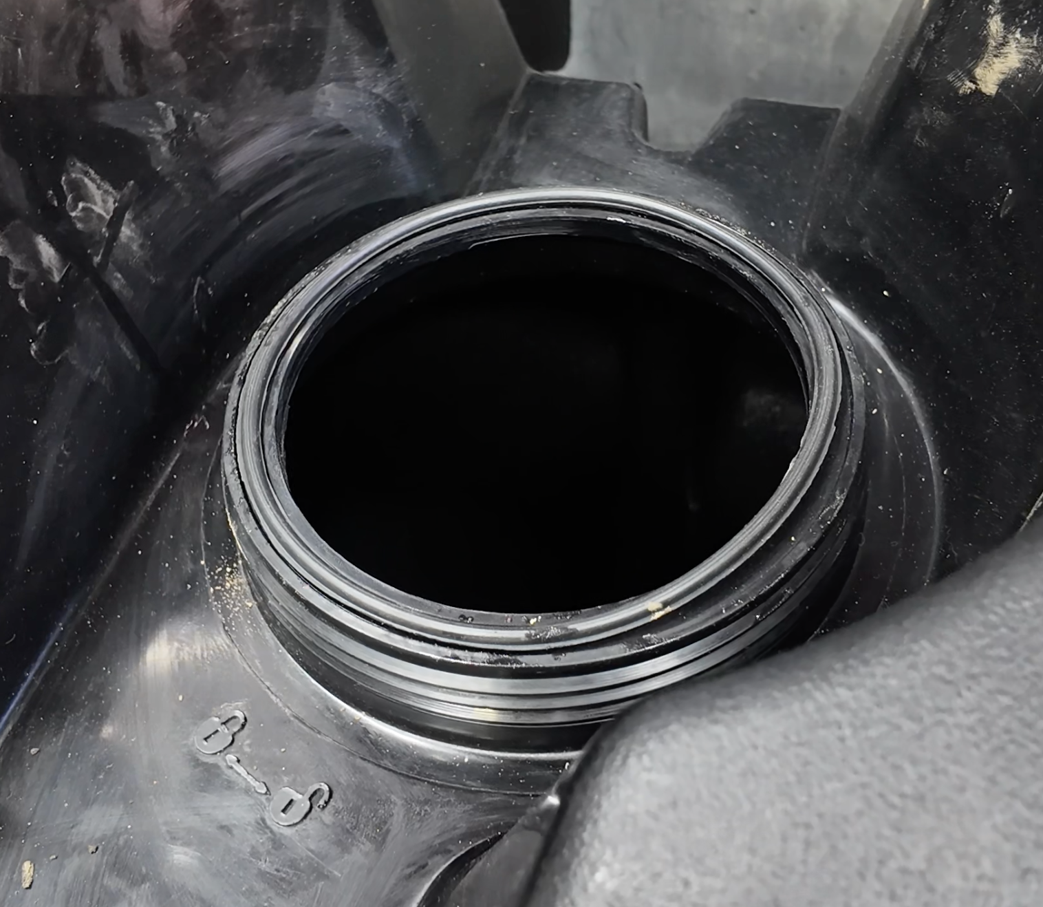
Using a small pry tool and rubber mallet, unscrew the ring by hitting it counter clockwise.
*Be careful to not break the tabs on the ring.
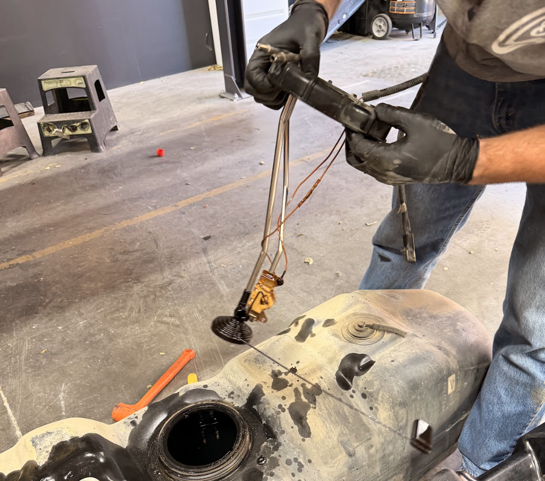
Remove the OEM sending unit from inside of the fuel tank.
*Be careful when removing the sending unit as to not break the float or foot at the bottom of the unit.
Check the inside of the Fuel Tank for any debris that may have landed in there during shipping/transit. Once done, go ahead and place the provided O-Ring on the S&B Fuel Tank.
Before re-installing the OEM Sending Unit, bend back the tabs under the sending unit to prevent it from coming into contact with the provided O-Ring.
.png?v=1765922556584)
Now, go ahead and re-install the sending unit. Using a pry tool and rubber mallet, screw the ring by hitting it clockwise.
*Be careful to not break the tabs on the ring.

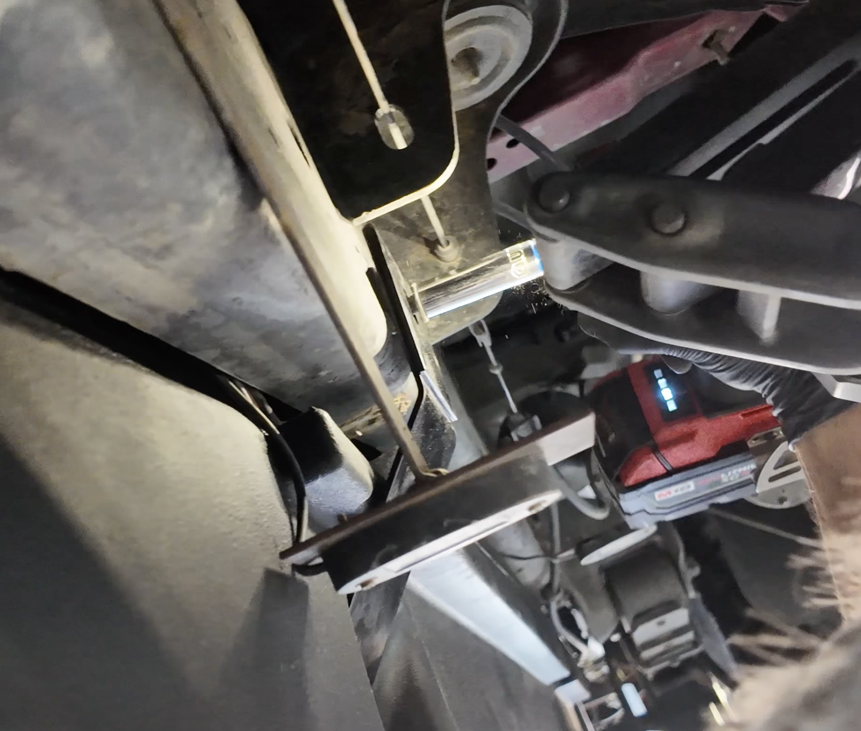
Place the provided U-bolt on the transfer case side of the forward most cross member, on the driver side frame rail (refer to Step 1).
.png?v=1765924266653)
Jack up the Fuel Tank in order to connect your 2x Fuel Lines and Electrical Connector.
.png?v=1765929290722)
Discard the slipnut on the left. *This was for the OEM Fuel tank Skid Plate.
Next, move the slipnut on the right to the left hole.
.png?v=1765930836459)
Now, it's time to mount the forward C-mount to the U-bolt from a previous step. Go ahead and leave the 2 nuts hand tight for right now.
Now, let's install the S&B middle hangar. Start by routing the driveshaft side first then go ahead and mount up the frame side using a 13mm socket.
Now its time to install the rear bracket for the fuel tank. Start by running the 90 degree section of the bracket in between the driveshaft and fuel tank in preparation for the next step. Then mount the frame side of the bracket. This will be located just behind and above the forward leaf spring hangar. You'll need a 13mm socket to do this.

Bolt up the cross-member side of the bracket (next to the driveshaft). This can also be done with a 13mm socket.

Now, go ahead and tighten down the front tank C-mount for the fuel tank using a 19mm socket.
Next, go ahead and run the rollover vent tube from the front of the fuel tank above the body mounts, along the frame rail, and to the fuel filler tube.
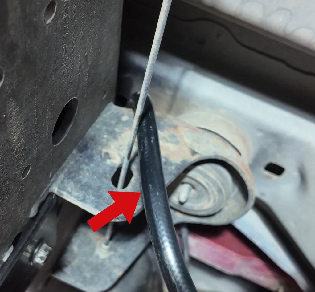
Reconnect the fuel filler tube (red arrow) and tighten down the hose clamp using an 8mm socket.
Then reconnect the vent tube (yellow arrow) and tighten down the hose clamp using an 8mm socket.
.png?v=1766000343980)
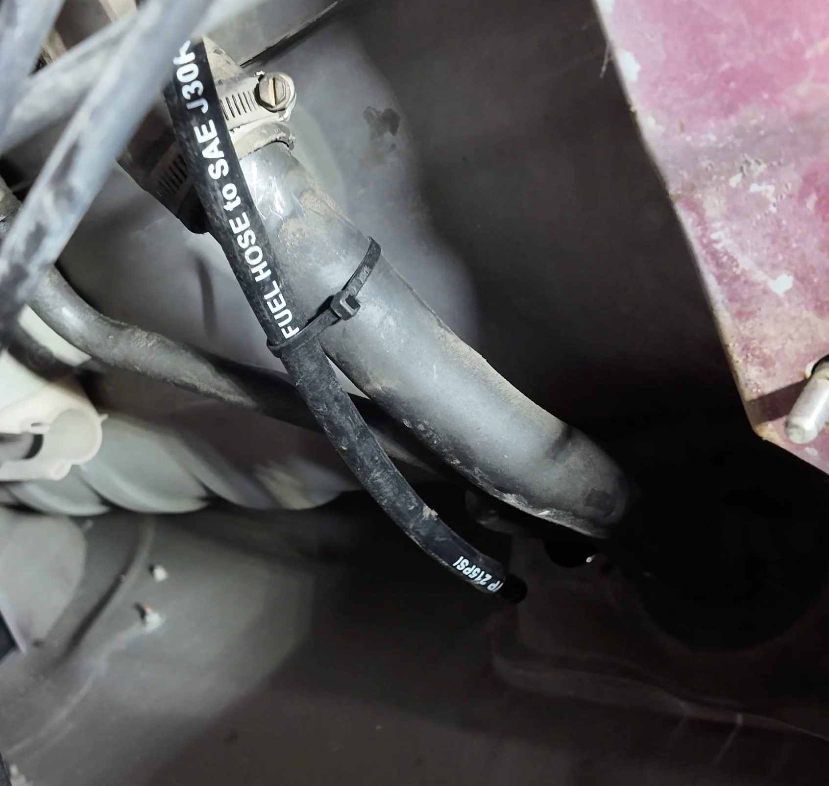
Take the rollover valve tube you ran along the upper frame rail and run it along the filler tube. Then zip tie it secure.
*Tip: There is another hose located at the rear of the fuel tank. We recommend securing it to a hole within the frame.
Verify that all connection points are tight and secure. Your installation is now complete.
