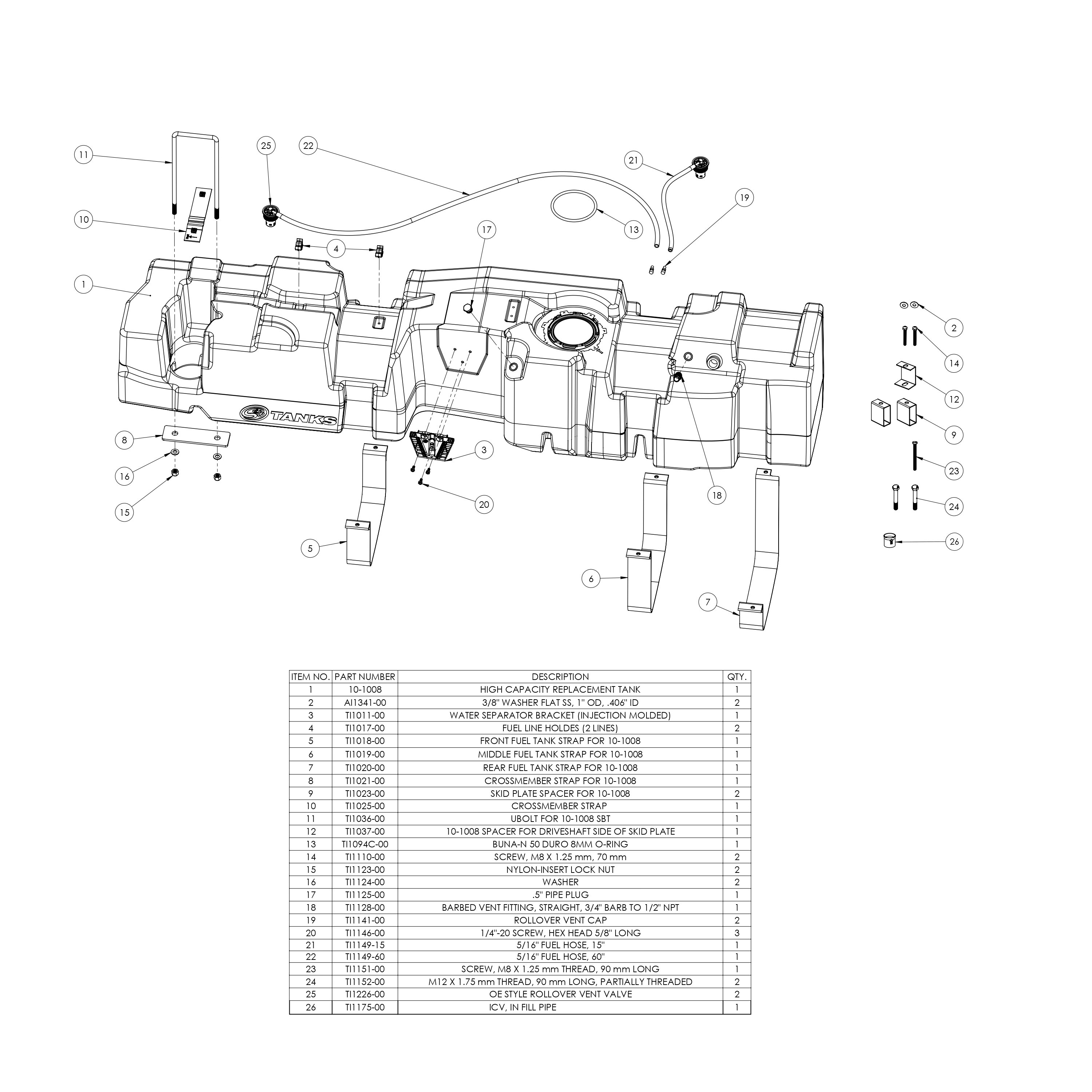
Step 1
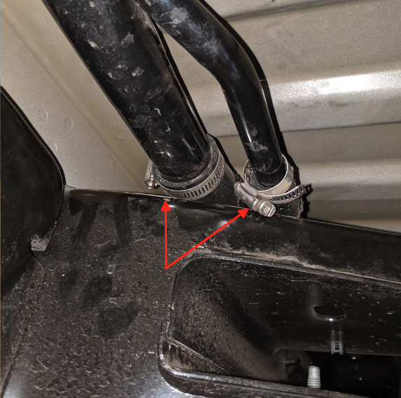
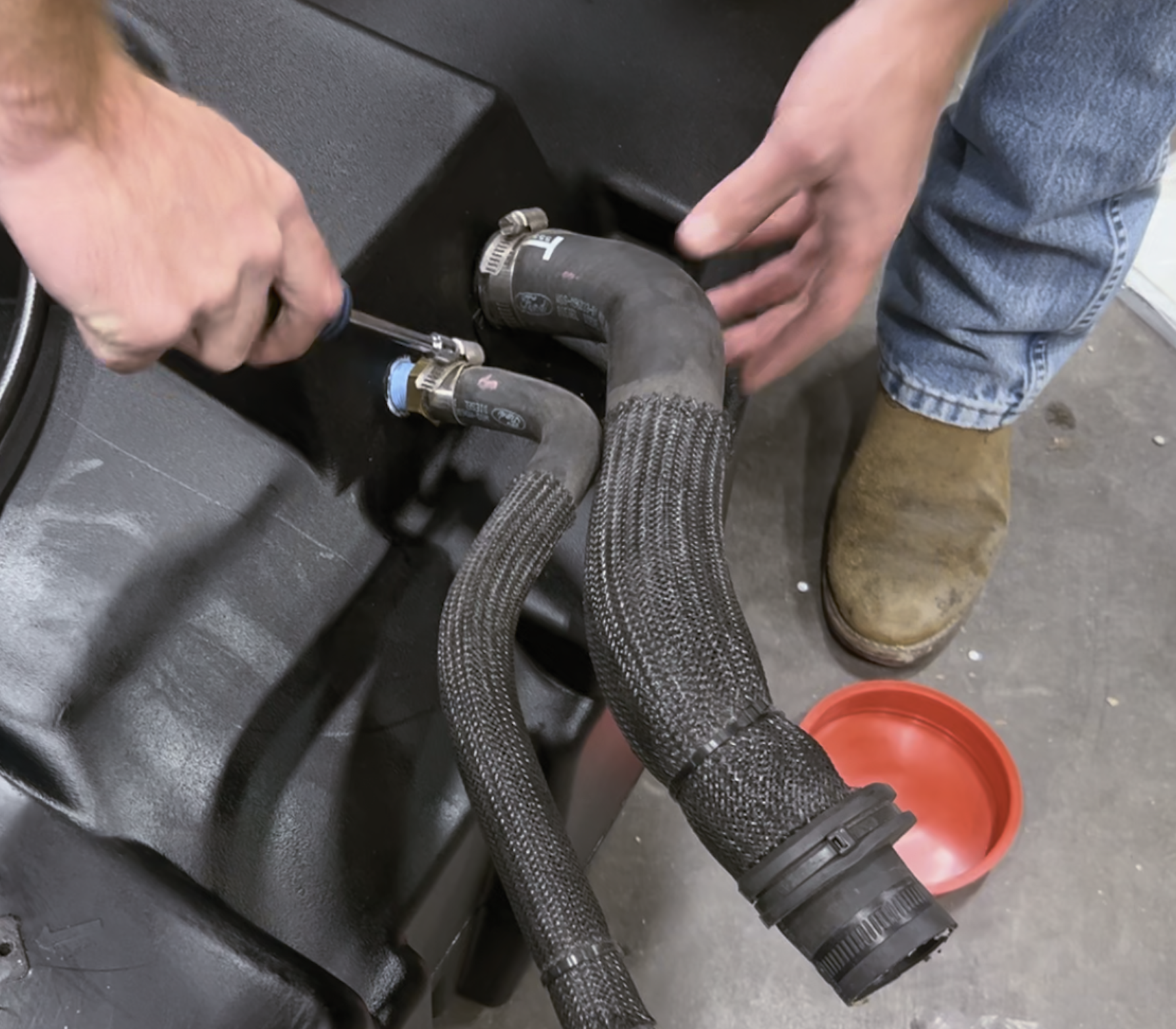
Remove the filler and vent hoses from the filler assembly. If the hose clamps are facing the bed, you can use a small 5/16” socket.
Important Note: Incorrect hardware was included with some of these tanks. If your tank came with the nuts on the left(black nylon), do not install them. The ones on the right are correct and are 1/2"-13. Please call us at 909.675.1313 to be sent correct hardware. If you don't want to wait 1 business day to receive these, hardware from a local hardware store can be used temporarily.
Remove the filler and vent hoses from the filler assembly. If the hose clamps are facing the bed, you can use a small 5/16” socket.
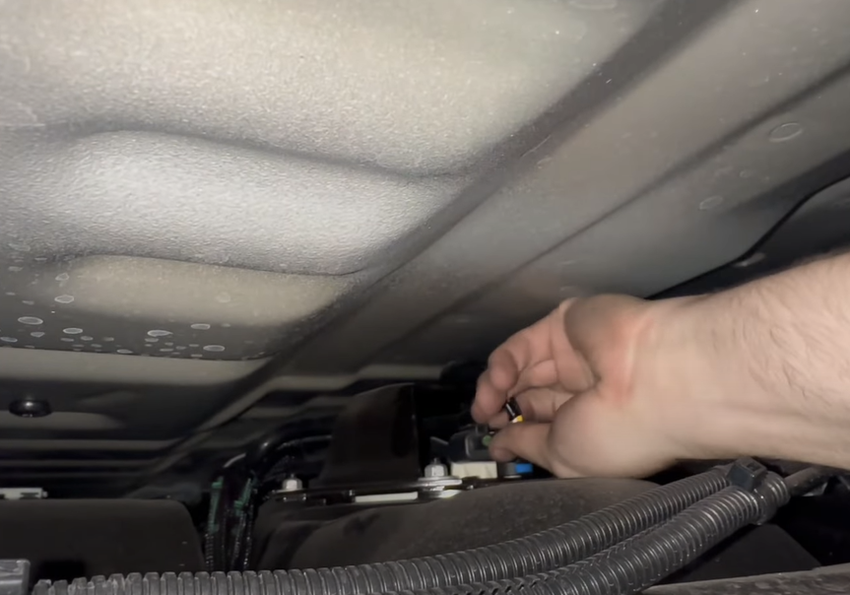
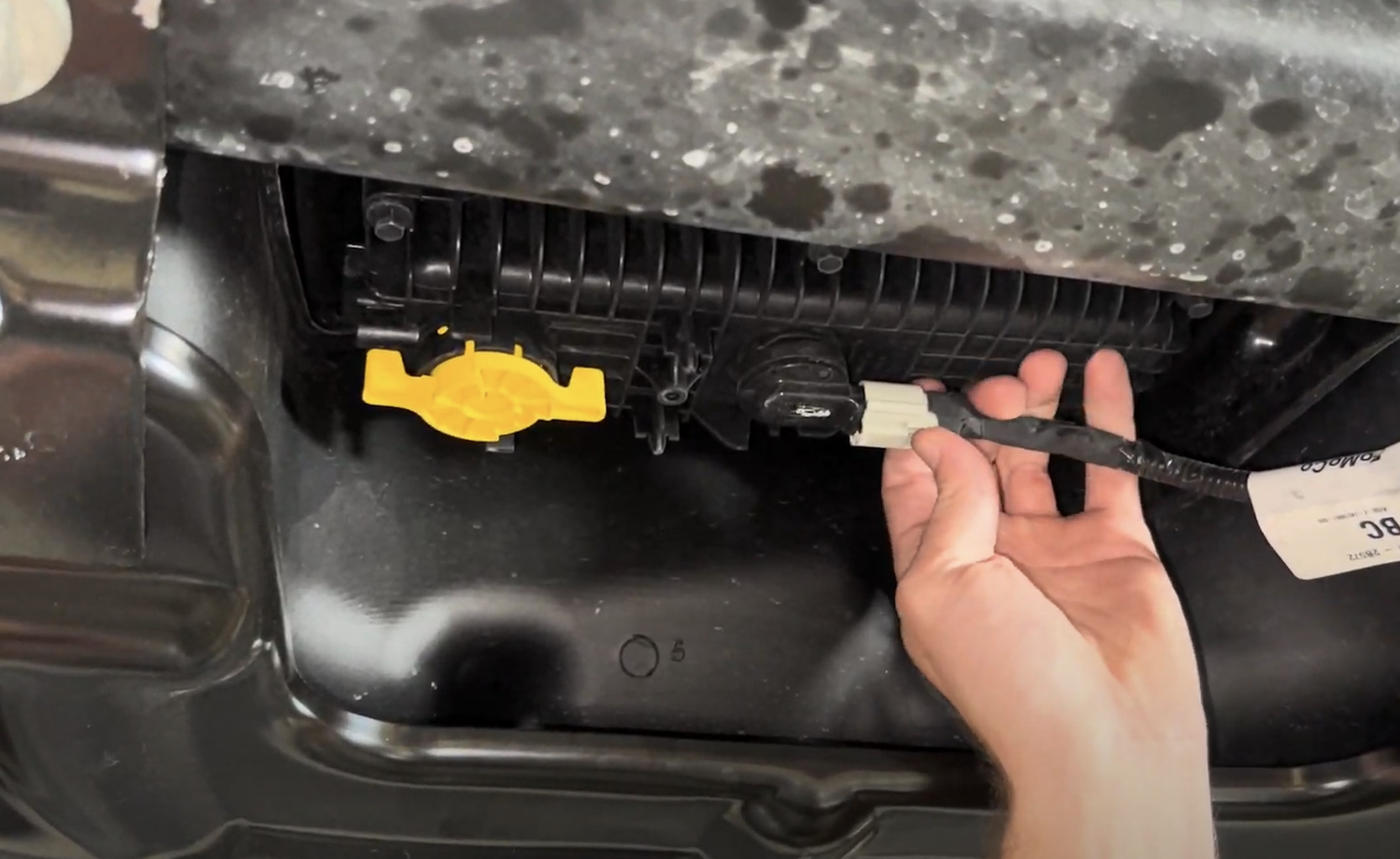
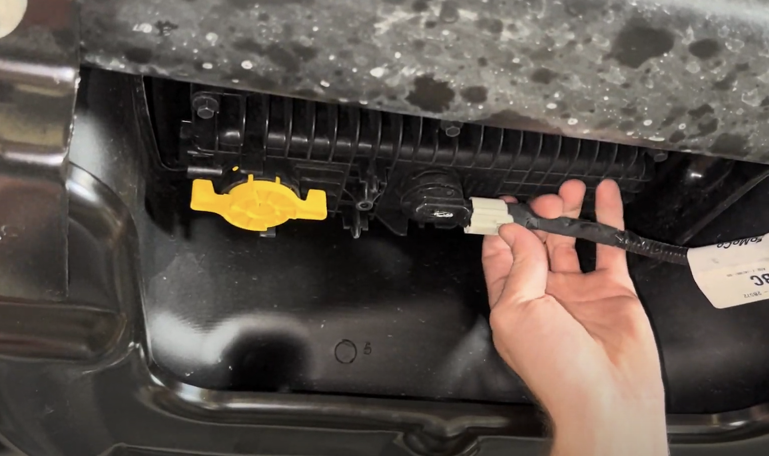
Reach over the frame rail to disconnect the electrical connection for the sending unit. Depress the tab and the connector will release.
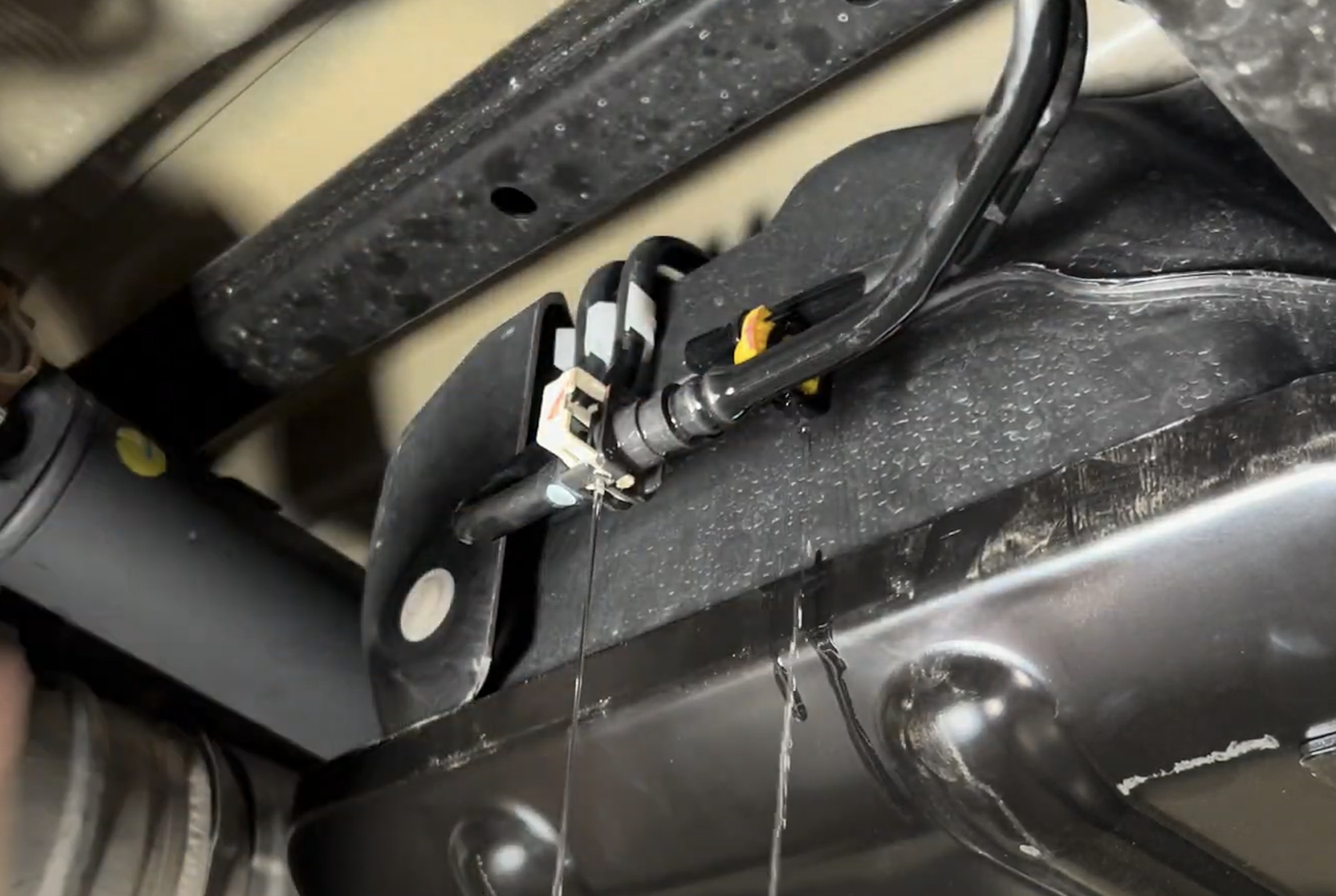
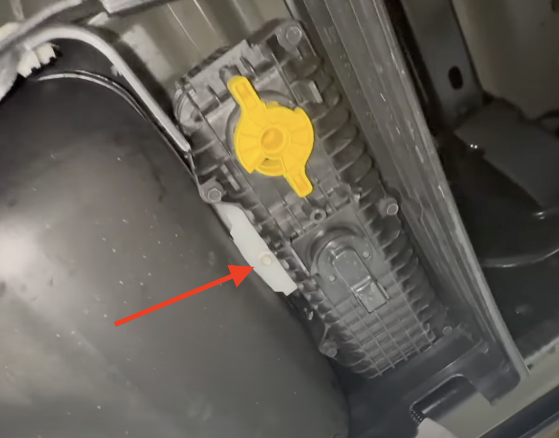
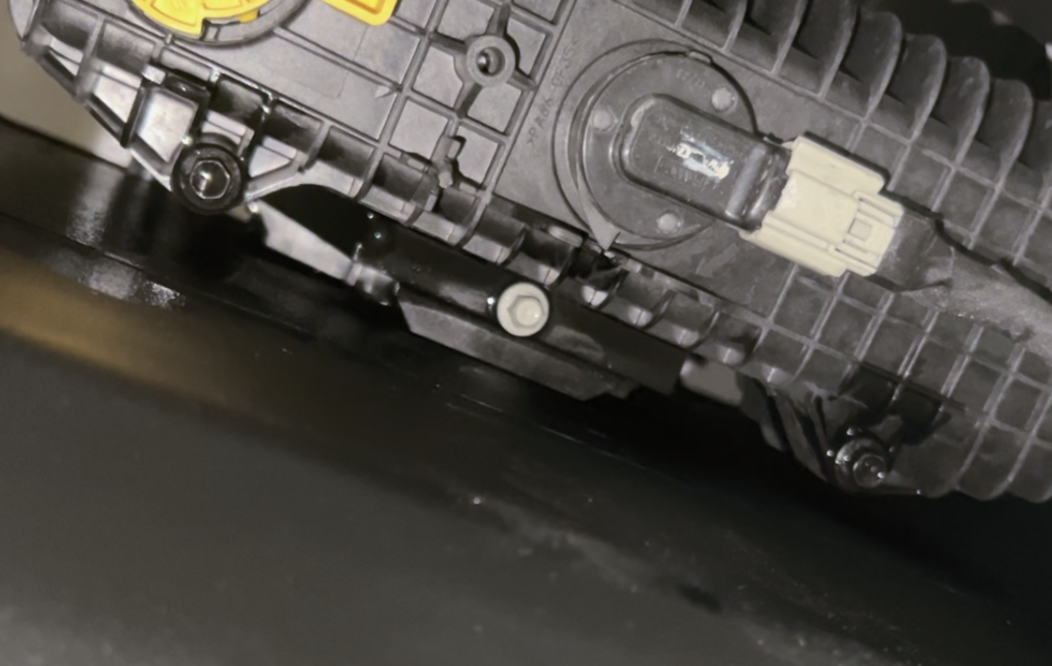
Remove the water in fuel sensor located on the bottom of the water separator. Depress the tab and the sensor will release.
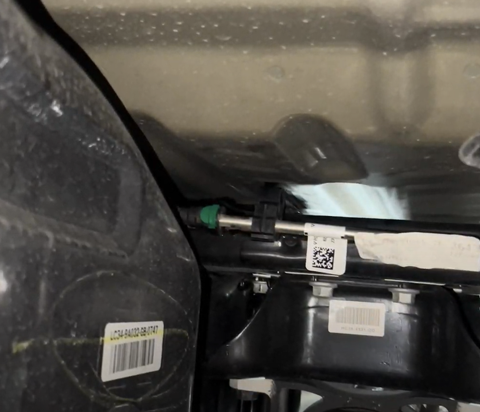
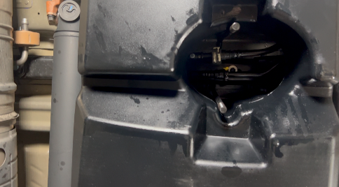
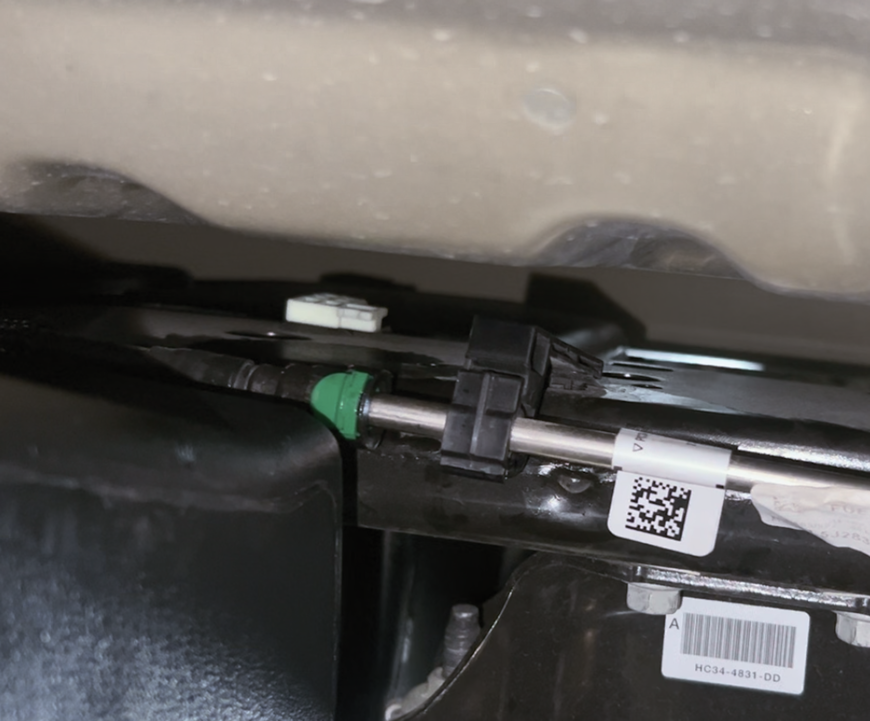
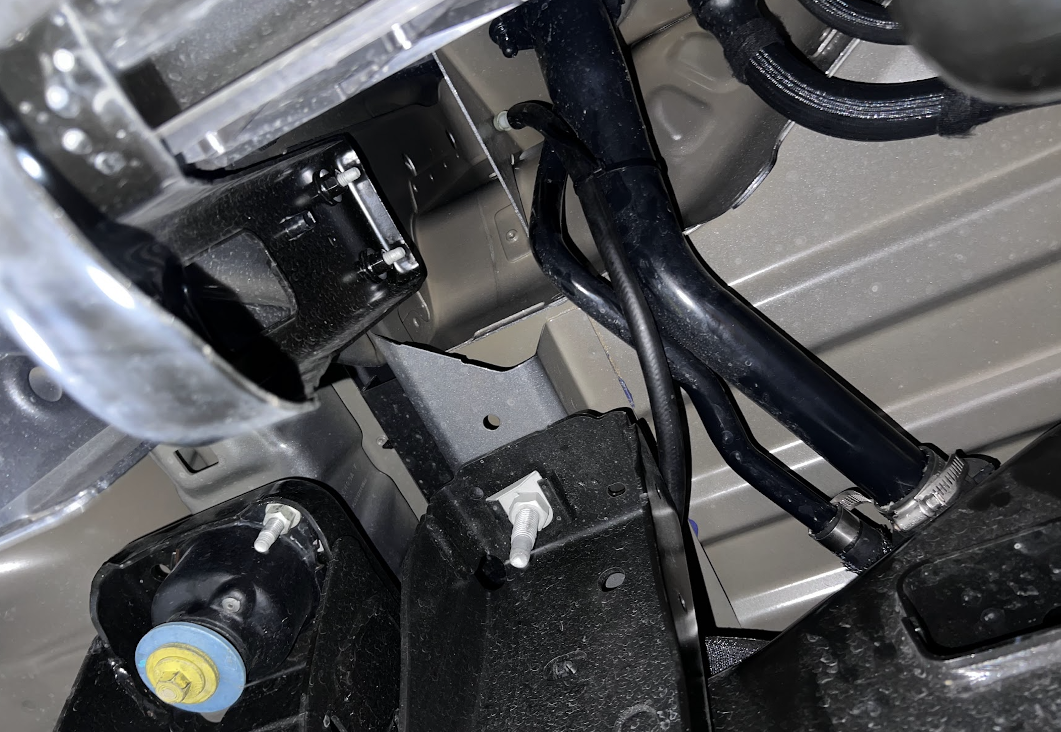
Remove the two fuel lines positioned in front of the fuel tank. For the red connector or white connector, slide the safety out and pull the connector apart.. For the yellow connector, pull the locking tab out(at the base of the connector) and depress the upper tab to remove the connector. Please see our install video if you need help
2023+ trucks, above the carrier bearing there is a fuel line going to the DPF. Disconnect this connector the way same way the yellow connector on the front of the tank was removed.
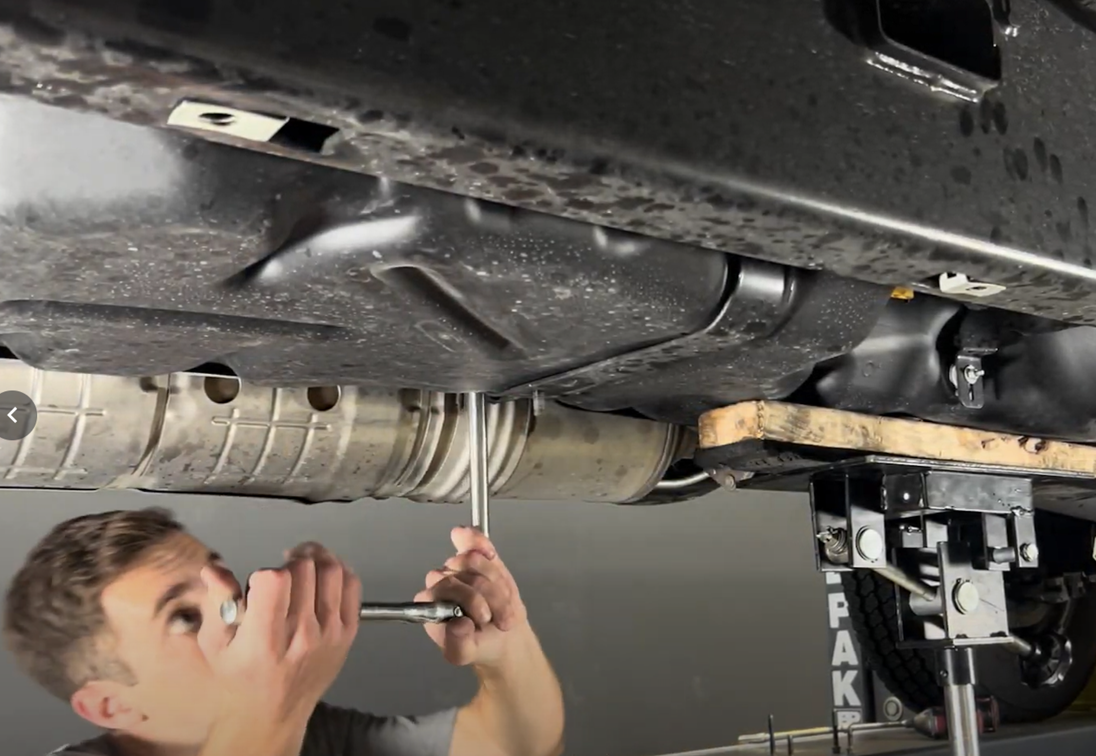
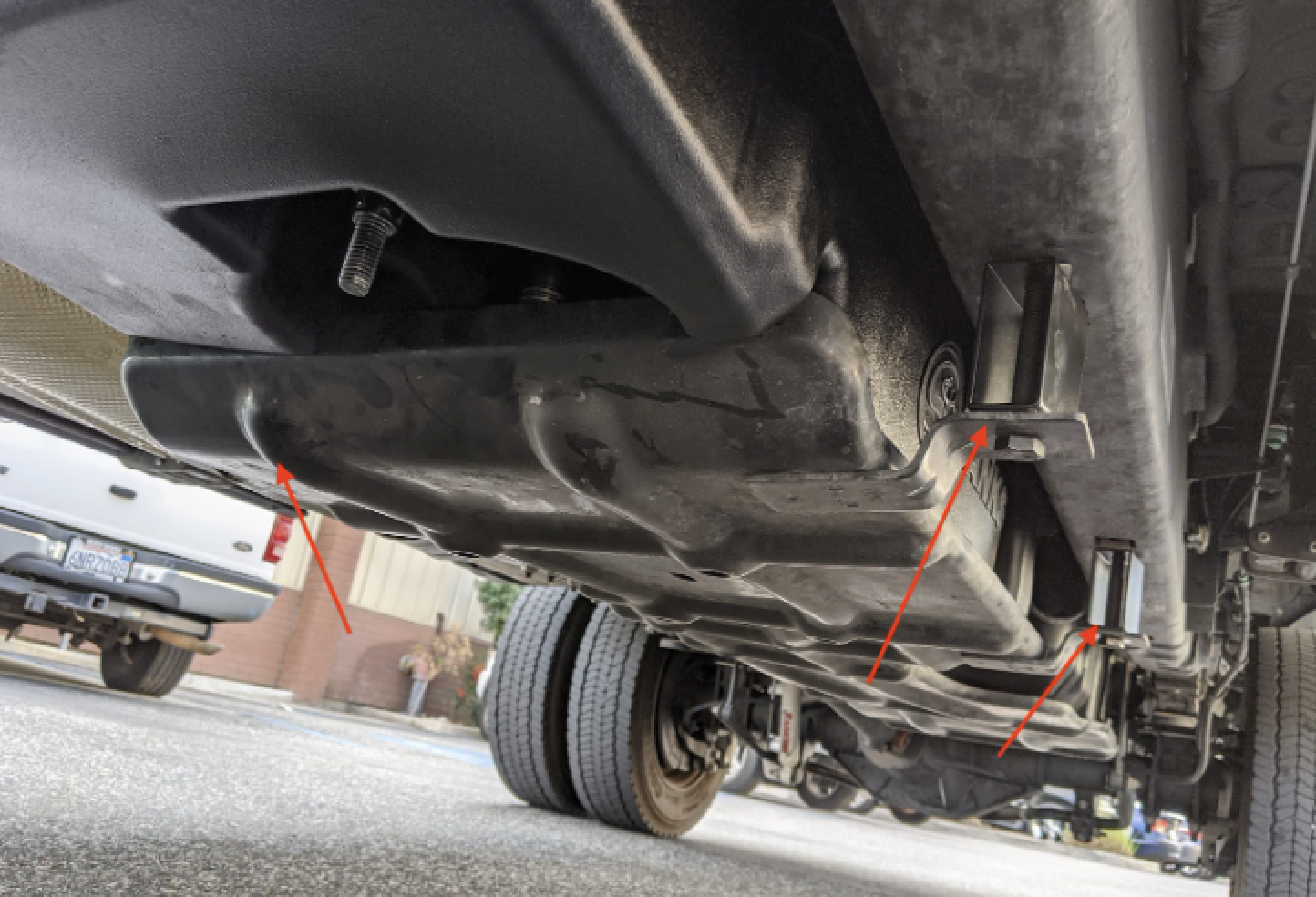
If your truck came equipped with a factory skid plate, now remove the skid plate. There are (2) 19mm head bolts (3) 13mm head bolts.
Remove the bolt holding the water separator to the bracket. 2017-19 trucks use a T-27 torx and 2020+ trucks use a 8mm.
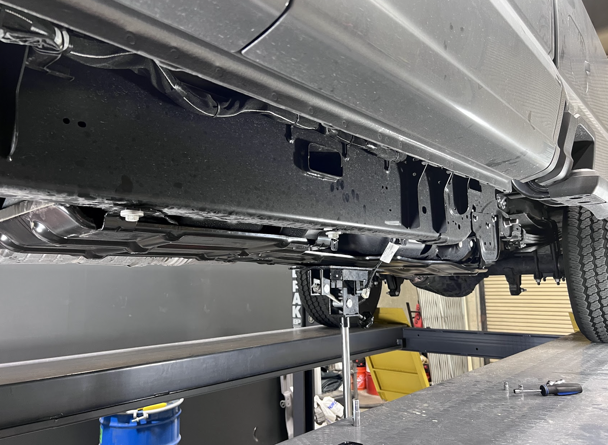
Remove the (6) 13mm head bolts holding the 3 tank straps in place. Do NOT use a drill/air ratchet or you risk spinning the cage nuts.
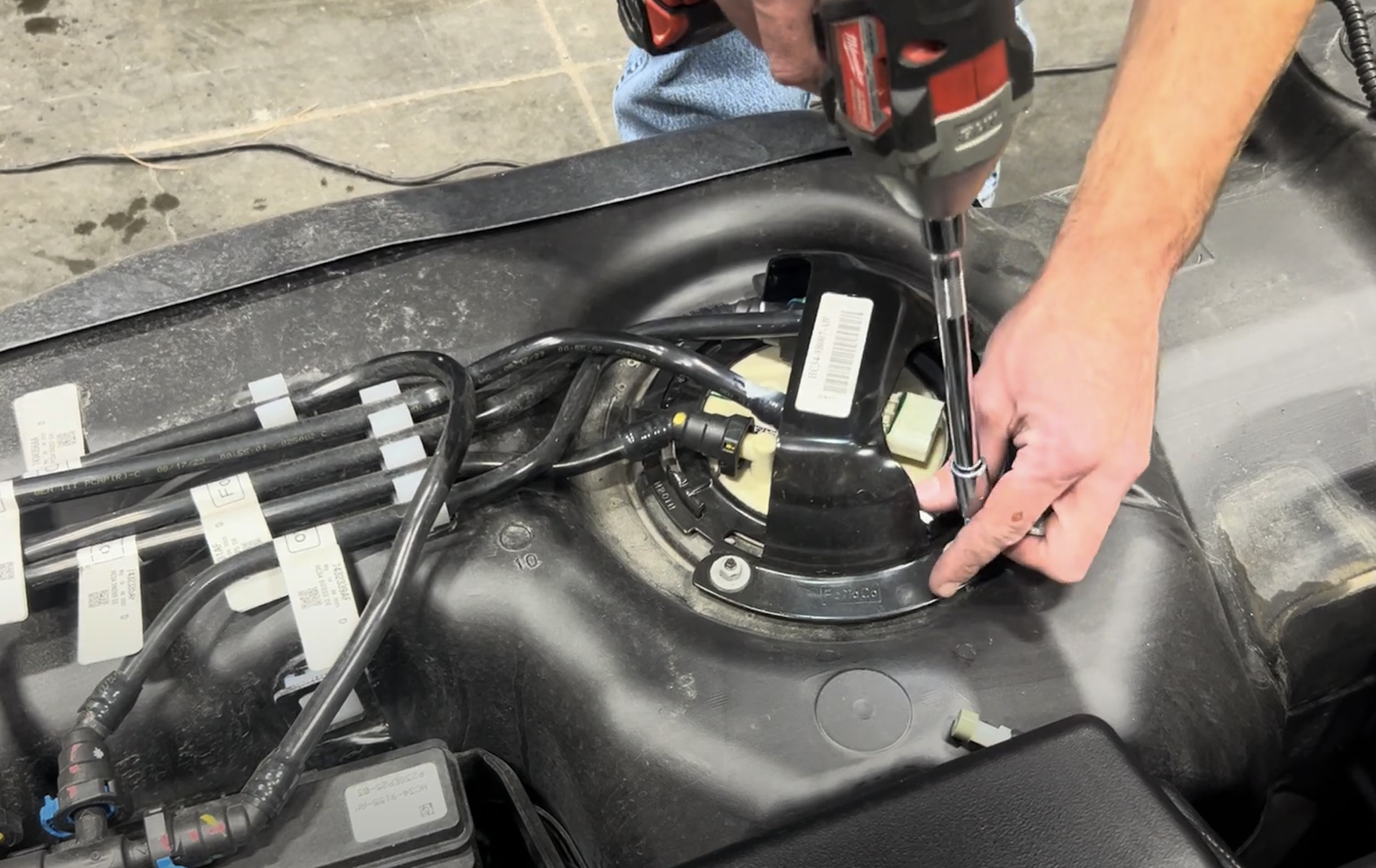
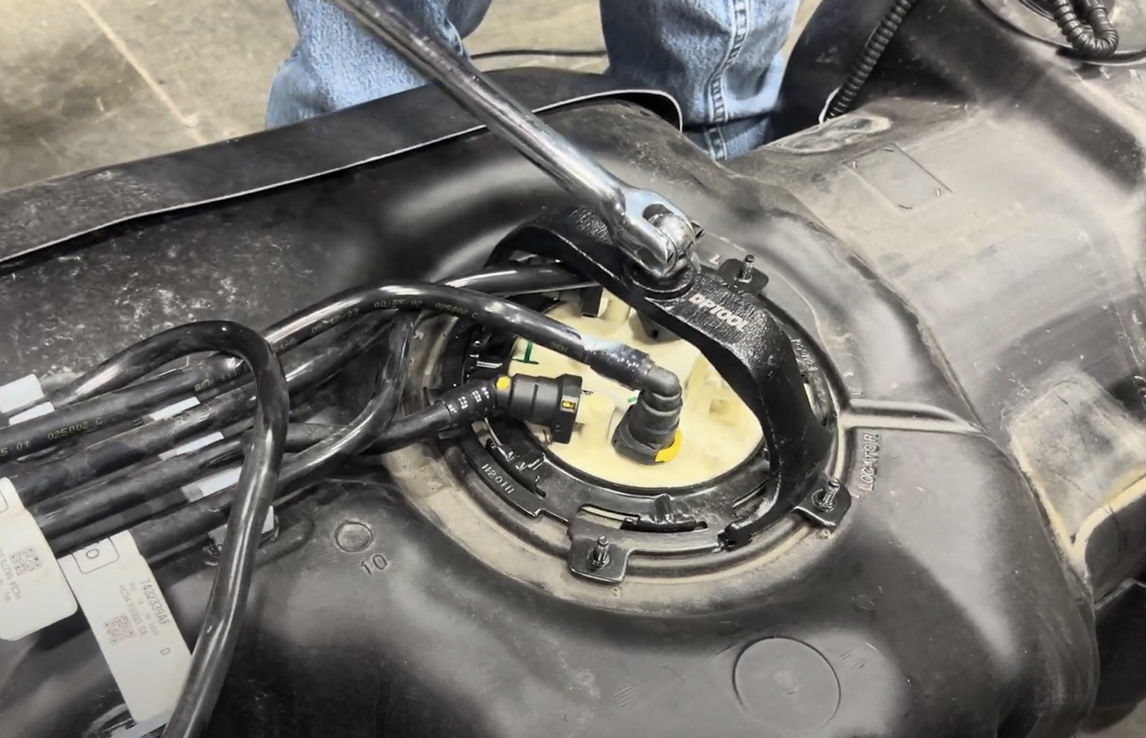
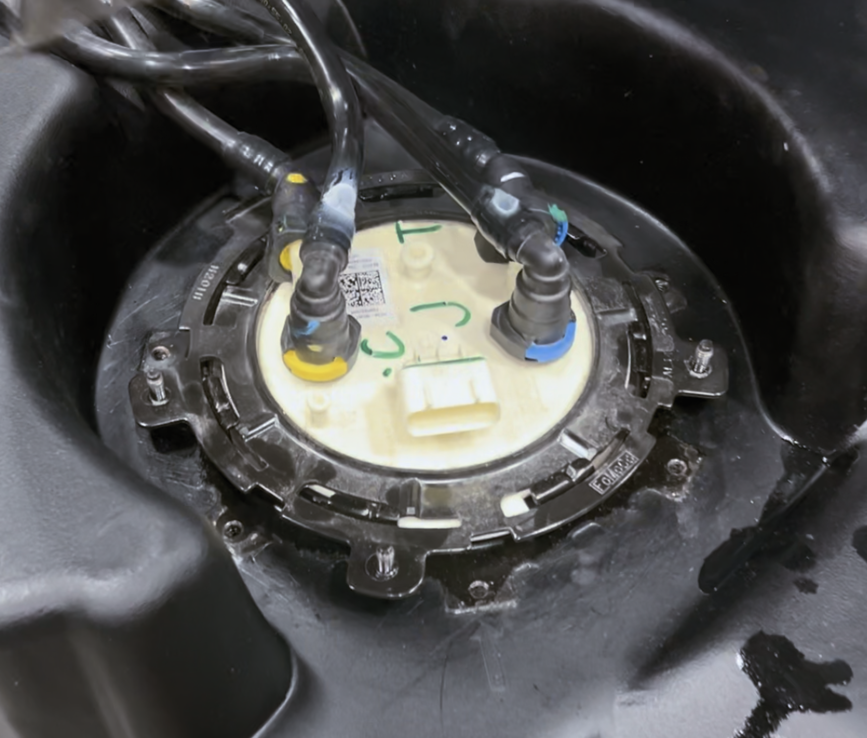
Remove the 3 nuts that hold the sending unit guard to the locking ring. It is important to remember the orientation of the sending unit guard.
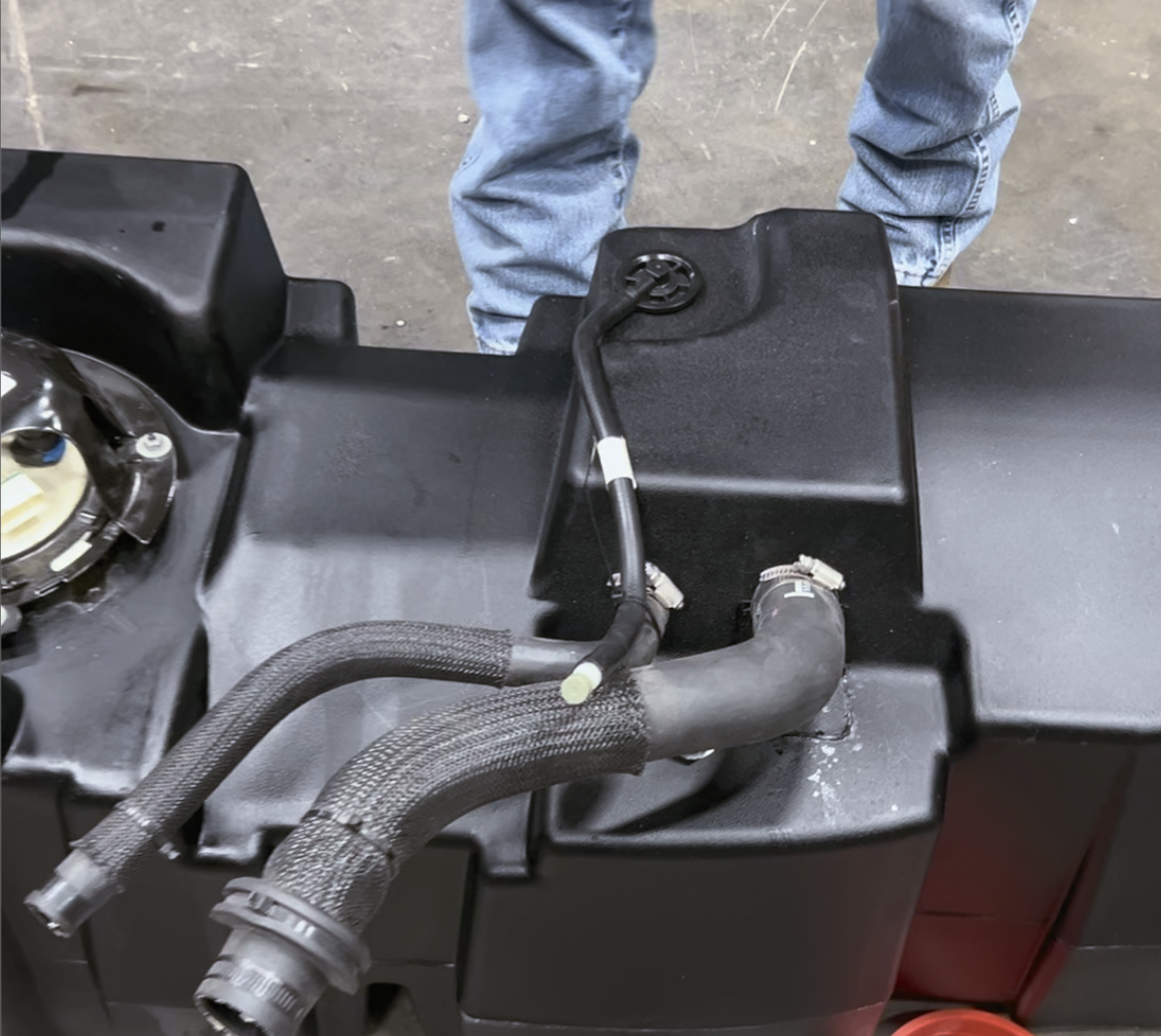
Remove the fuel lines from the fuel line holders on the OEM tank.
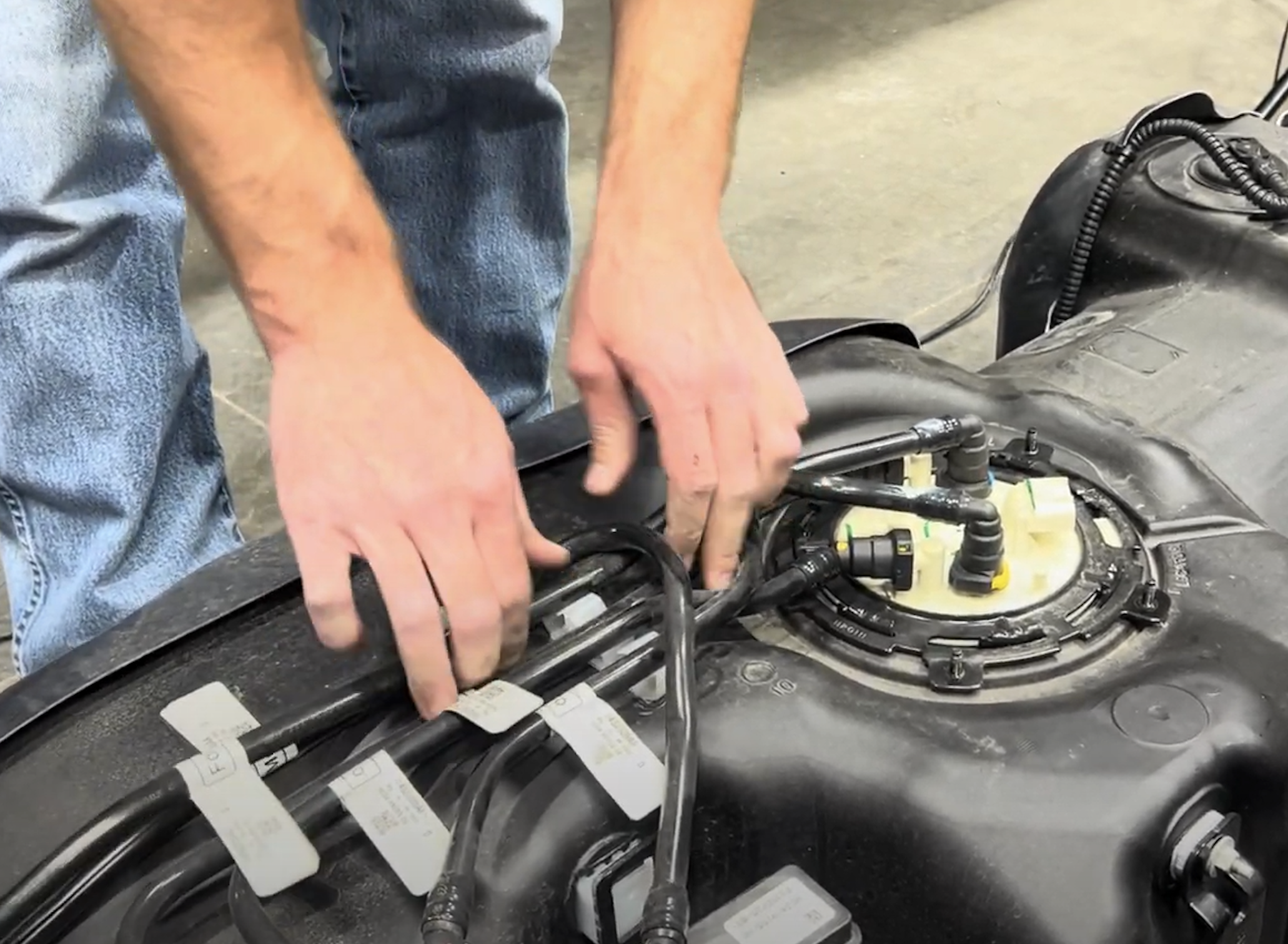
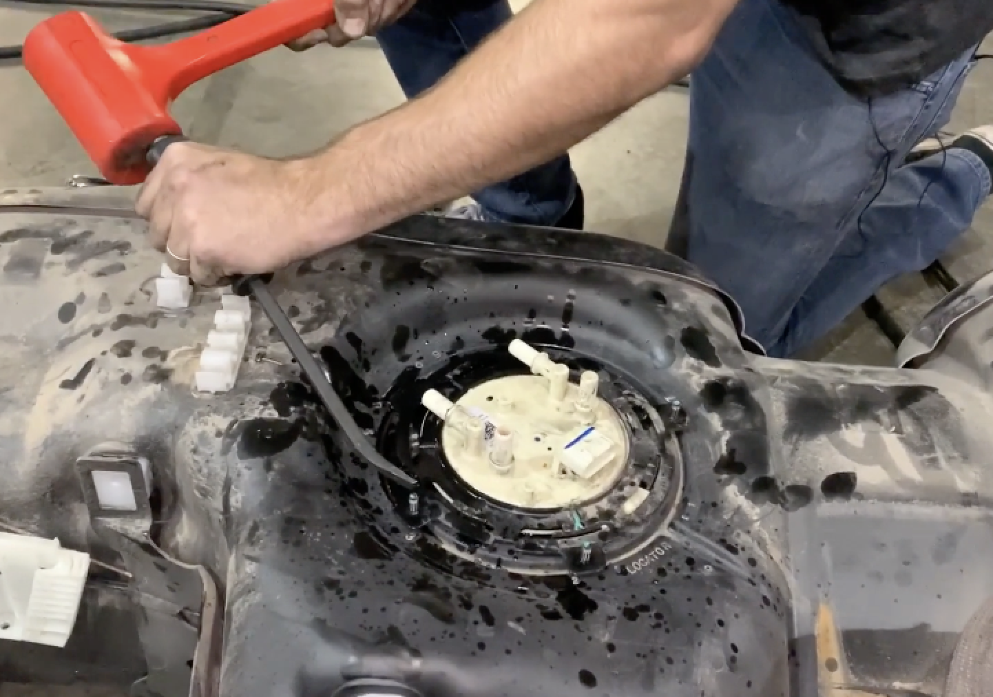
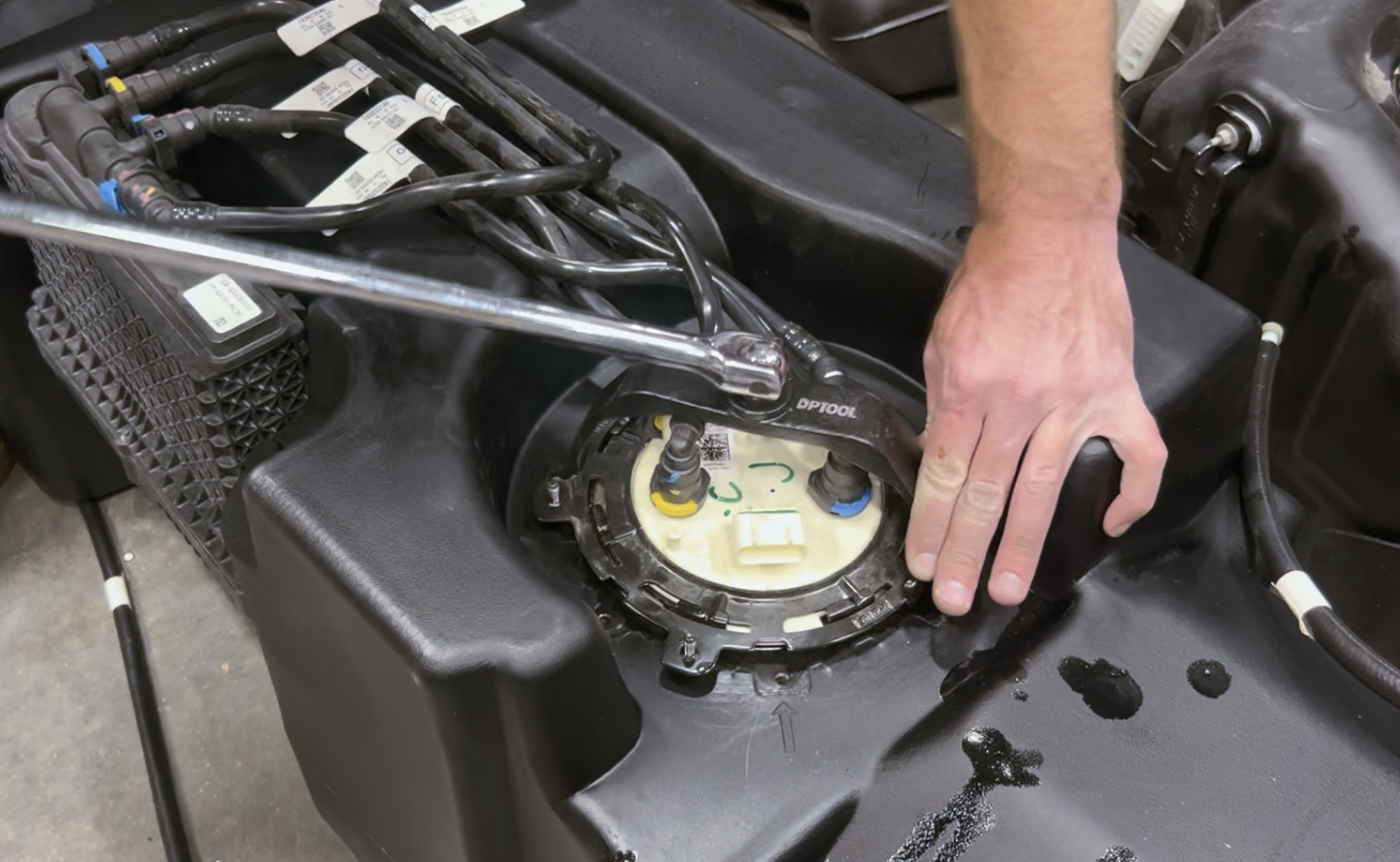
With a locking ring removal tool or dead blow/prybar, rotate the locking ring counterclockwise.
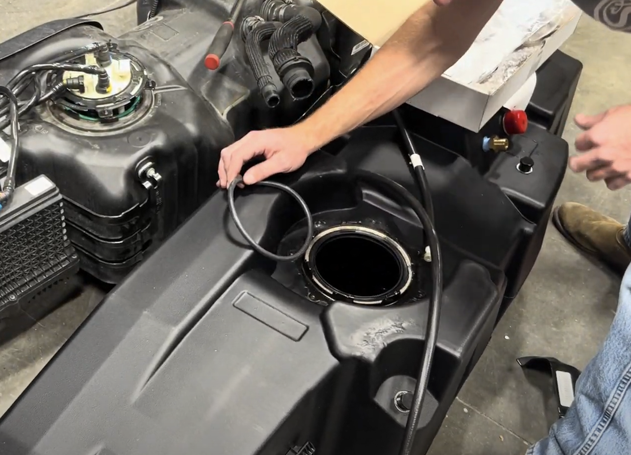
Inspect the inside of the tank with a flashlight. Then install the provided black S&B oring. If you install the green Ford oring, the tank will leak.
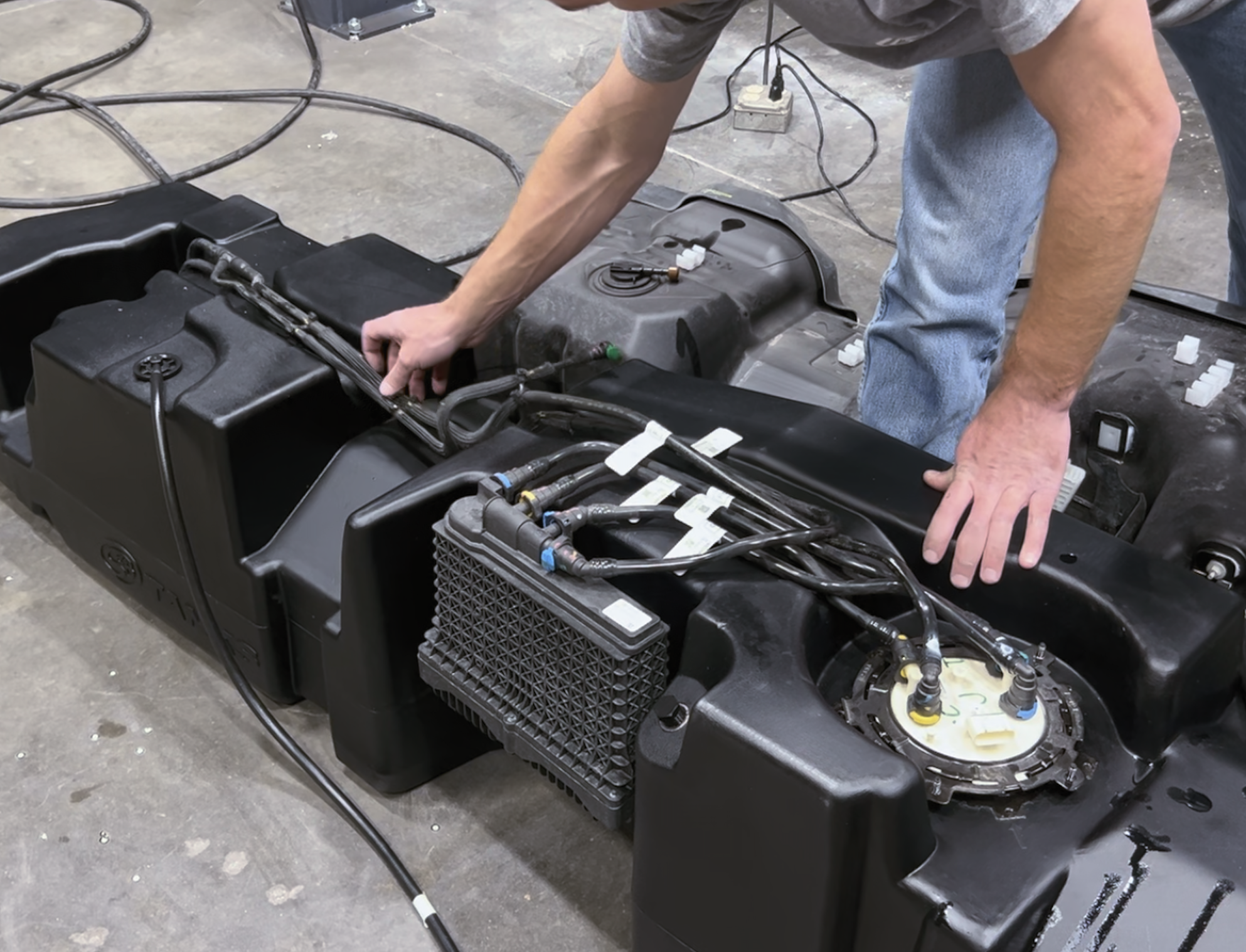
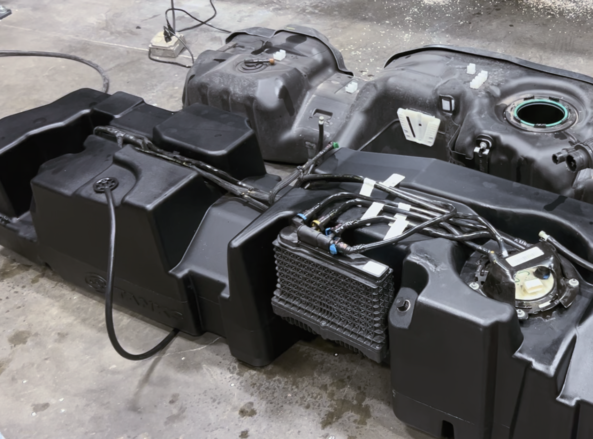
Transfer the OEM sending unit, water separator and fuel lines from the OEM tank to S&B Tank
Make sure the locking ring is positioned the same way as it was on the OEM tank so the guard will still allow access to the electrical connector. Once confirmed, press down on the ring to get the ring started under the teeth on the ring.
Use the fuel locking ring tool or dead blow/prybar to rotate the ring clockwise until it passes under the indention on the receiving ring.
Snap the fuel lines into the S&B tank and seat the water separator
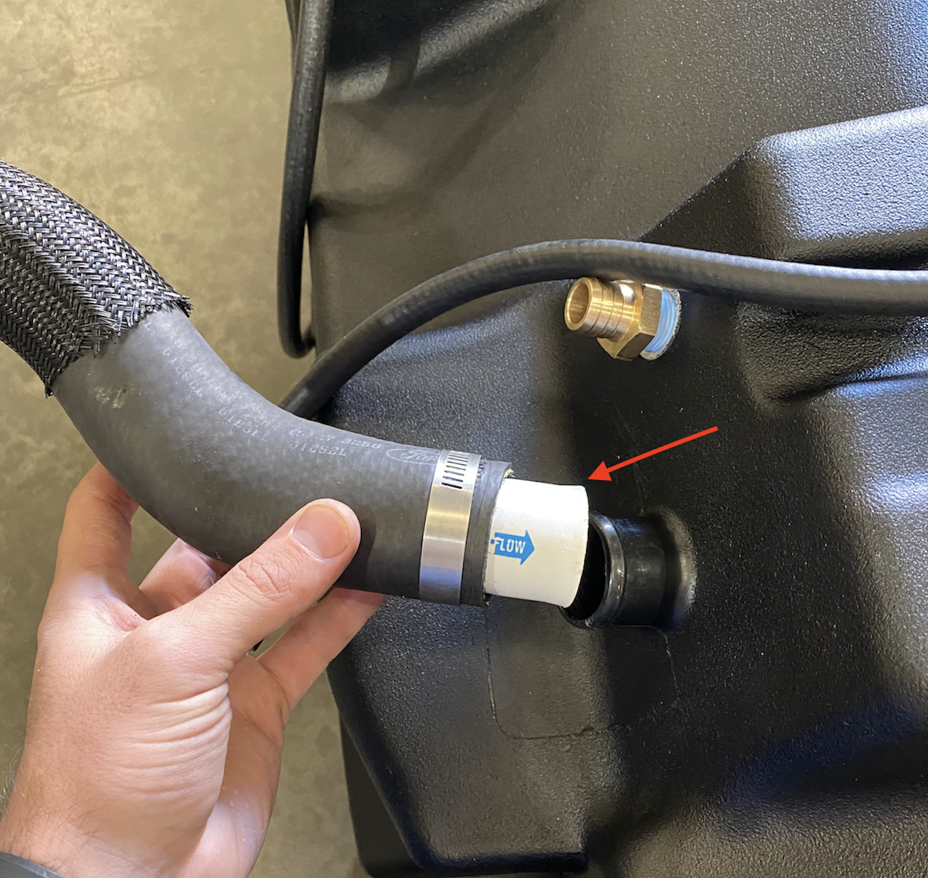
Transfer the filler and vent hose to the S&B Tank. Insert the check valve into the filler prior to installing the hose with the arrow facing into the S&B Tank.
Zip tie the breather vent to the ¾’ main vent
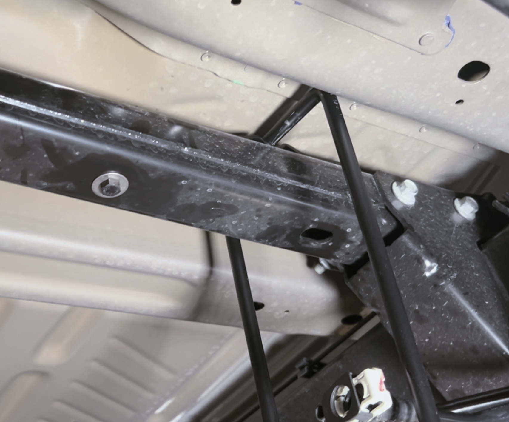
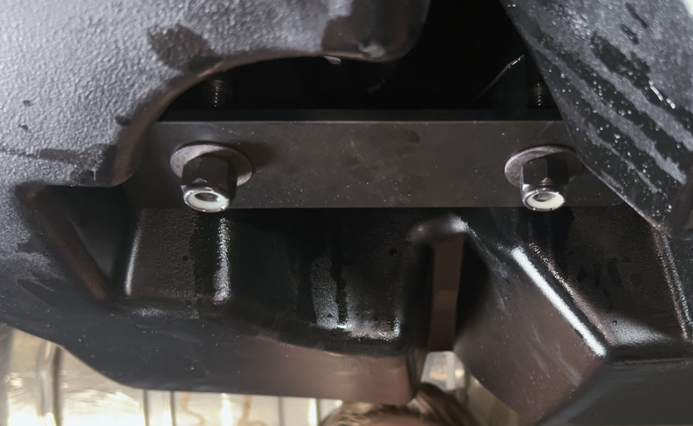
Install item # 9 on top of the crossmember with the ubolt resting in the channel of #9. Install the (2) 13mm head bolts with washers to keep the bracket and ubolt in place
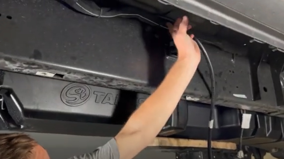
Now the tank is ready to be lifted into place. As your lift the tank into place, route the route breather hose over the crossmember, make sure the filler and vent go over the crossmember and make sure the ubolt falls into place in the front cutout.
Reconnect the (2) fuel lines. After they are connected, gently try to pull them apart to make sure they are fully installed.
2023+ trucks, reconnect the DPF injector line.
Reconnect the water in fuel electrical connector.
Reinstall the bolt for the water separator. Some trucks use a T-27 Torx and other trucks have a 8mm bolt head.
Install the 3 S&B Tank straps and front S&B support. Tighten the tank straps bolts to (30 lb.ft (40 Nm). Use a 19mm socket to tighten the nuts on the front tank support plate. Do not use an impact on the front support, the plate should be snug against the tank.
Route the front breather hose to the filler and zip tie so its facing up the filler. Reconnect the filler and vent hoses and tighten the hose clamps. If you do not have a OEM skid plate, the install is now complete. Please proceed to the last step to ensure the install is checked.
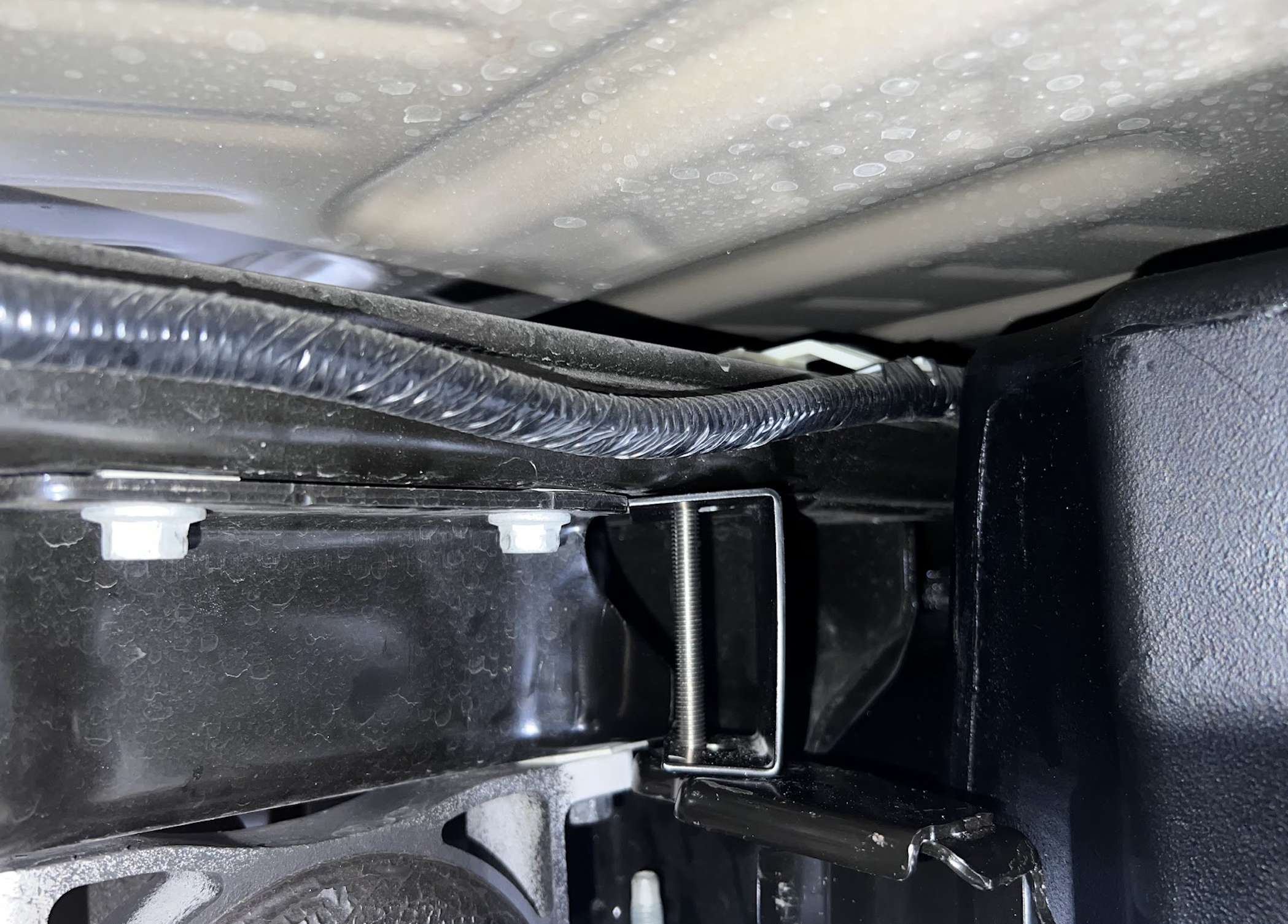
To reinstall the OEM skid plate, the front hanger on the driverline side needs to be spaced down and same with the front 2 on the frame side. Install the C shaped spacer between the crossmember and hanger. The longer section will go against the crossmember.
This final checklist is very important!
#1 Make sure all bolts and nuts are safely fastened and torqued
#2 Ensure there is proper driveshaft clearance
#3 If you reinstalled the OEM skid plate, make sure all the edges of the skid plate can't rub the tank. If they are, you'll need to bend the edges of the skid plate and/or add washers to the skid plate spacer.
#4 Double check the fuel line connections, the electrical connection, as well as the vent and fill lines.
#5 Lastly, fill the tank and check for any leaks.
If you have any questions, call or text 909.675.1313