STEP 1
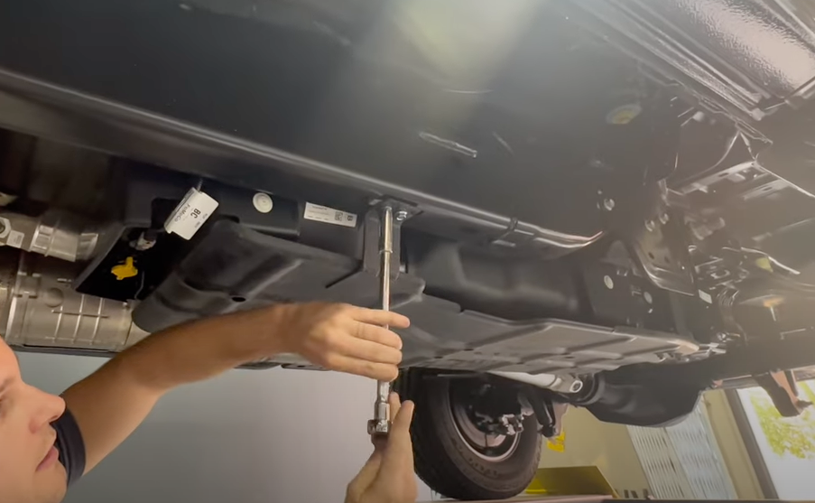
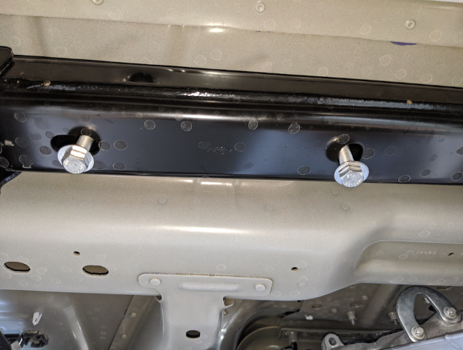
If the truck came with a OEM skid plate, remove the (6) 13mm head bolts.
- Disconnect and isolate both of the negative battery cables
- Before installing S&B Tank, conduct pressure test to ensure o'ring is properly seated.
- In-bed Auxiliary Fuel Tanks will void the Lifetime Warranty.
- Nozzle at high flow fuel station may continue to "click off". Tank is designed to work at regular fuel stations.
If the truck came with a OEM skid plate, remove the (6) 13mm head bolts.
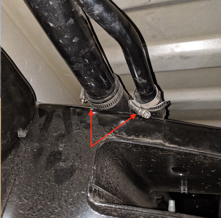
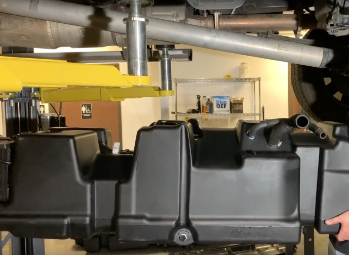
Remove the hose clamps with a short 5/16" socket/ratchet. If you are having trouble removing the hose then you can wait until everything is removed from the tank and then pull from the driveline side.
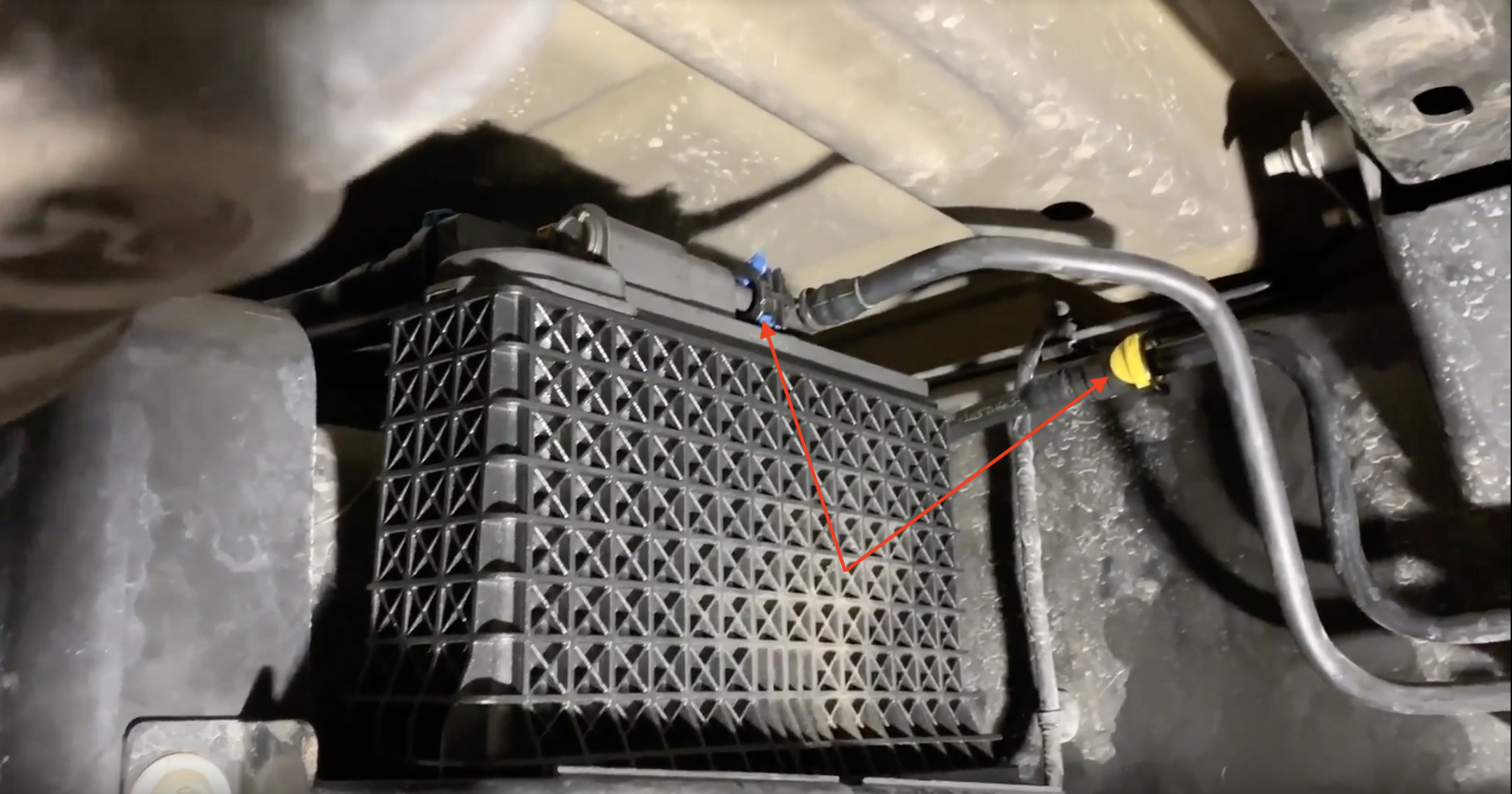
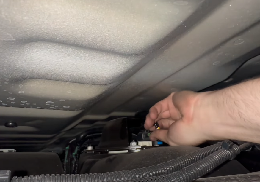
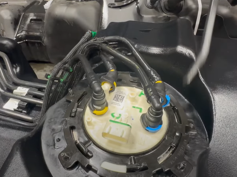
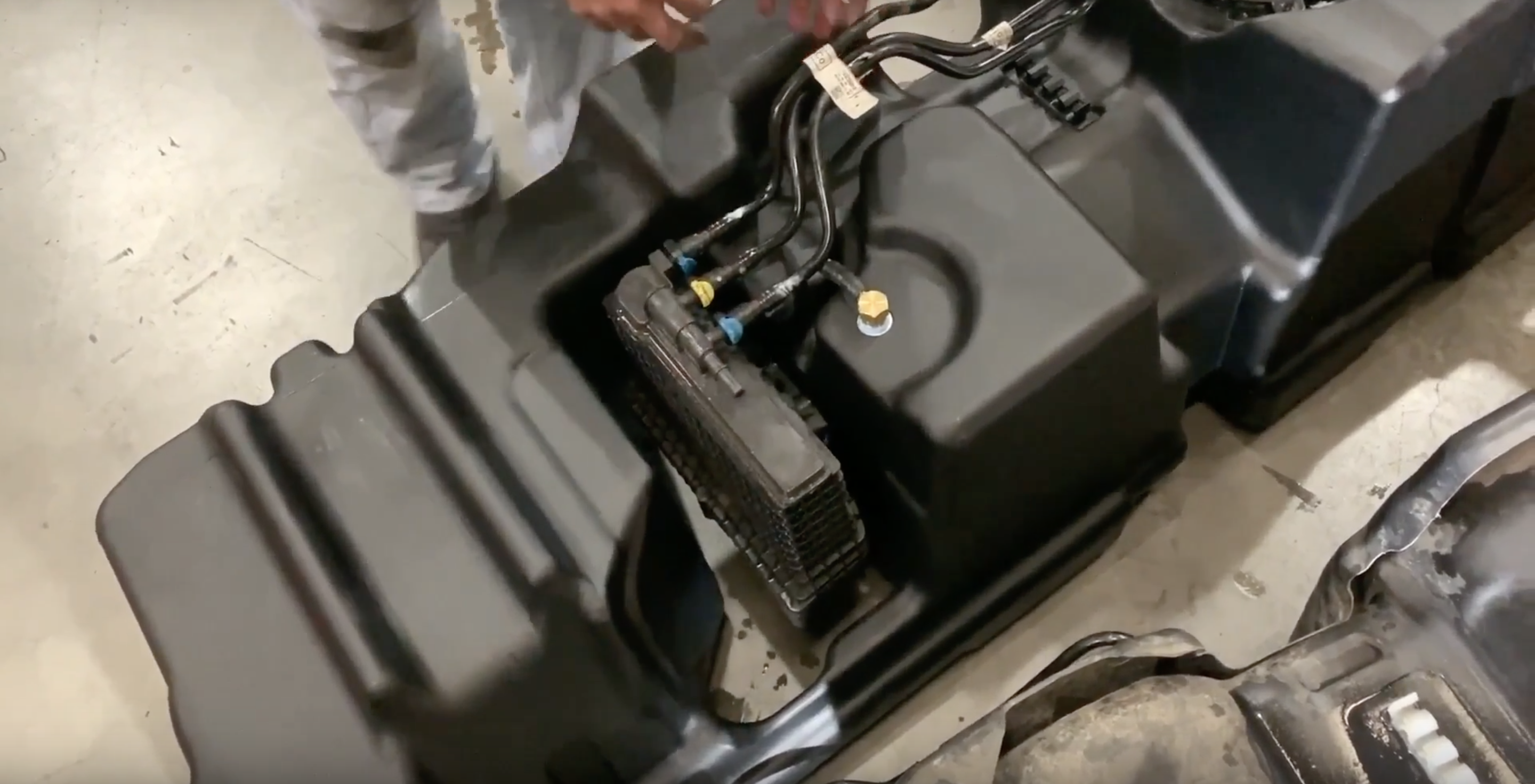
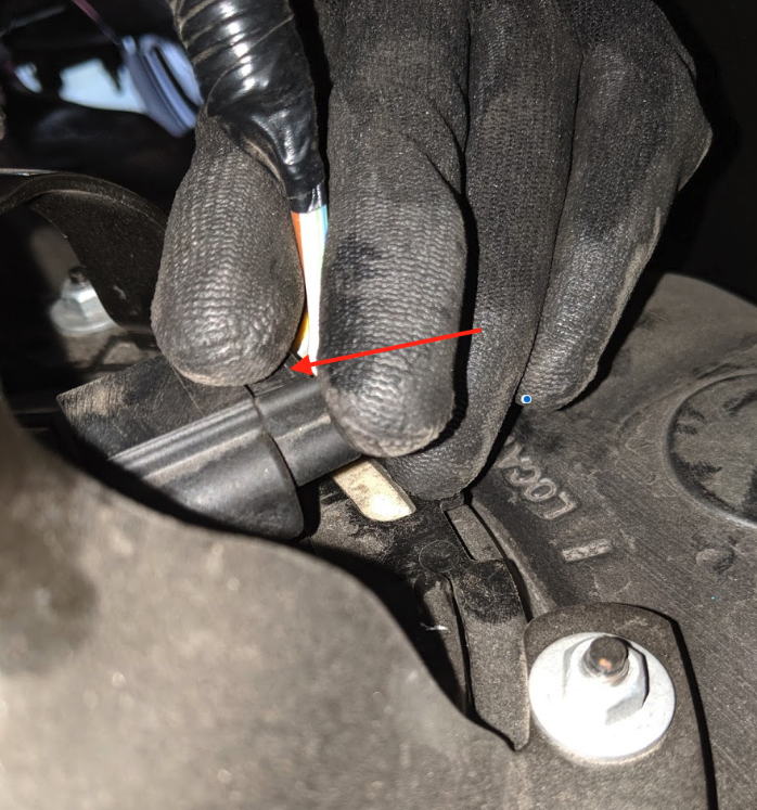
Remove the two fuel lines positioned on top of the fuel water separator. For the blue connector, push both tabs towards the rear of the vehicle and remove the line. For the yellow connector, pull the locking tab out and depress the upper tab to remove the connector.
Be careful with these connectors, they are known to break. Refer to this video to see just how to remove them.
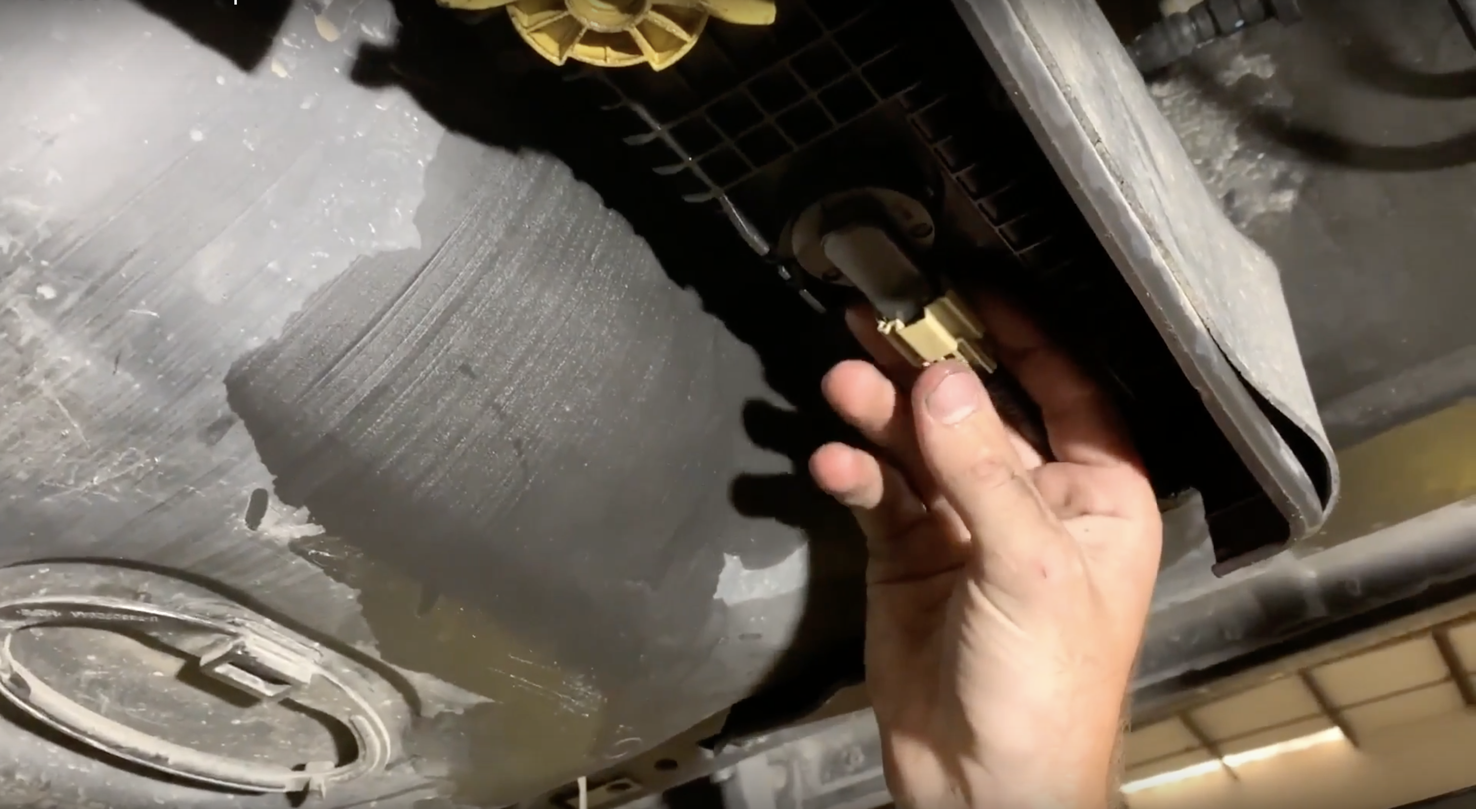
Remove the water in fuel sensor located on the bottom of the water separator. Depress the tab and the sensor will release.
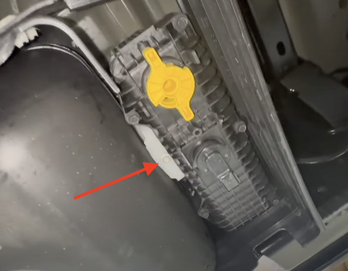
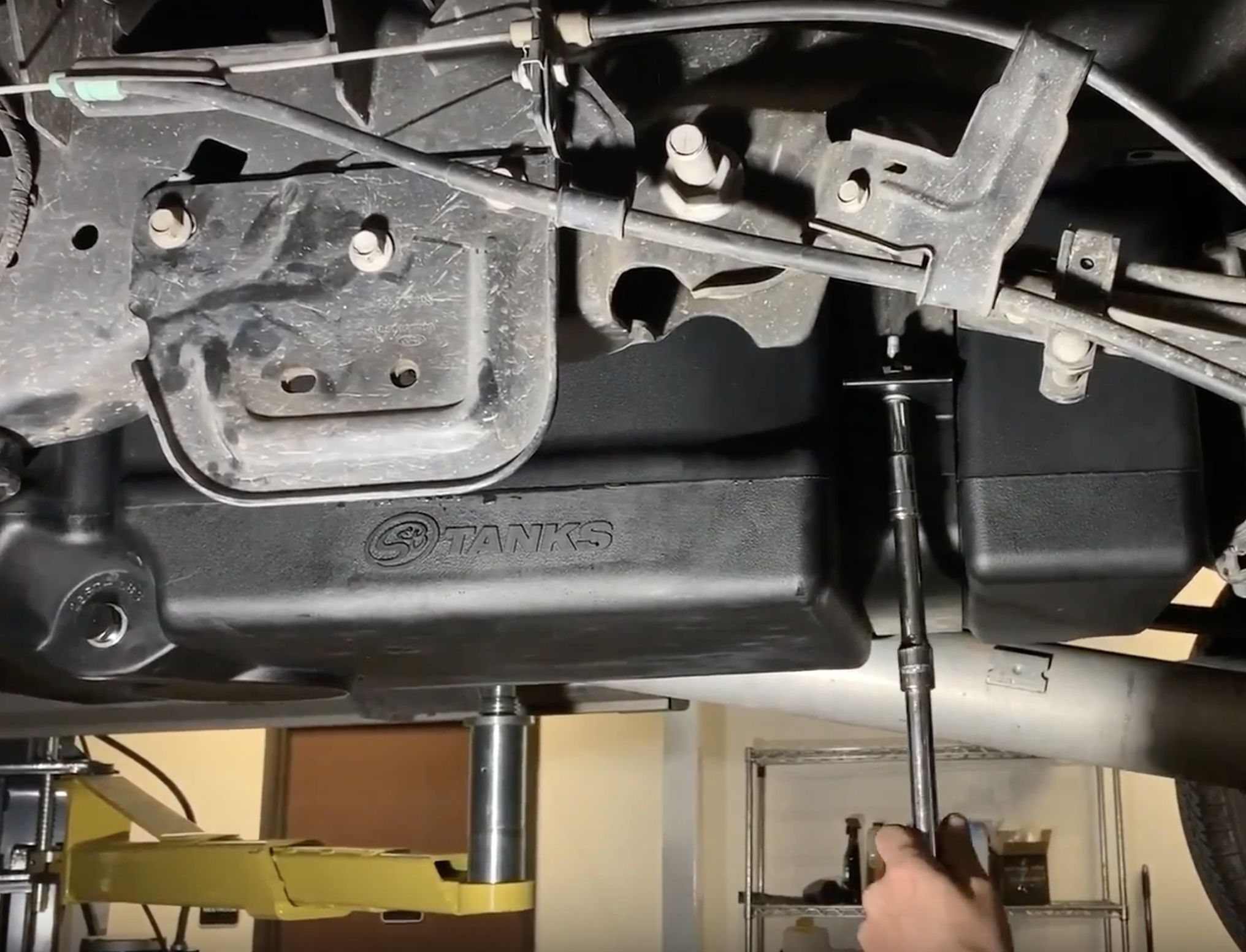
Remove the bolt holding the water separator to the bracket. 2017-19 trucks use a T-27 torx and 2020+ trucks use a 8mm.
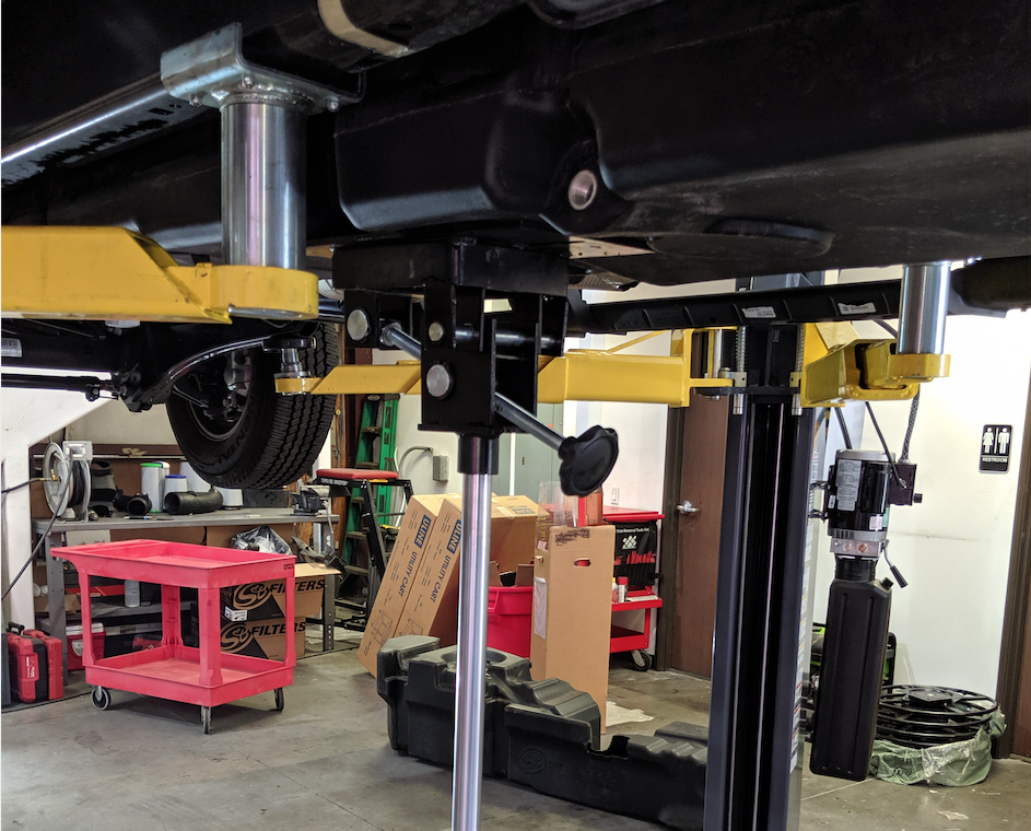
Center the hydraulic jack underneath the fuel tank and raise until the jack contacts the tank. If you can't reach the connected in step 7 without lowering the tank, drop the tank 6". Caution: Support the tank properly as remaining fuel can slosh and cause the tank to shift.
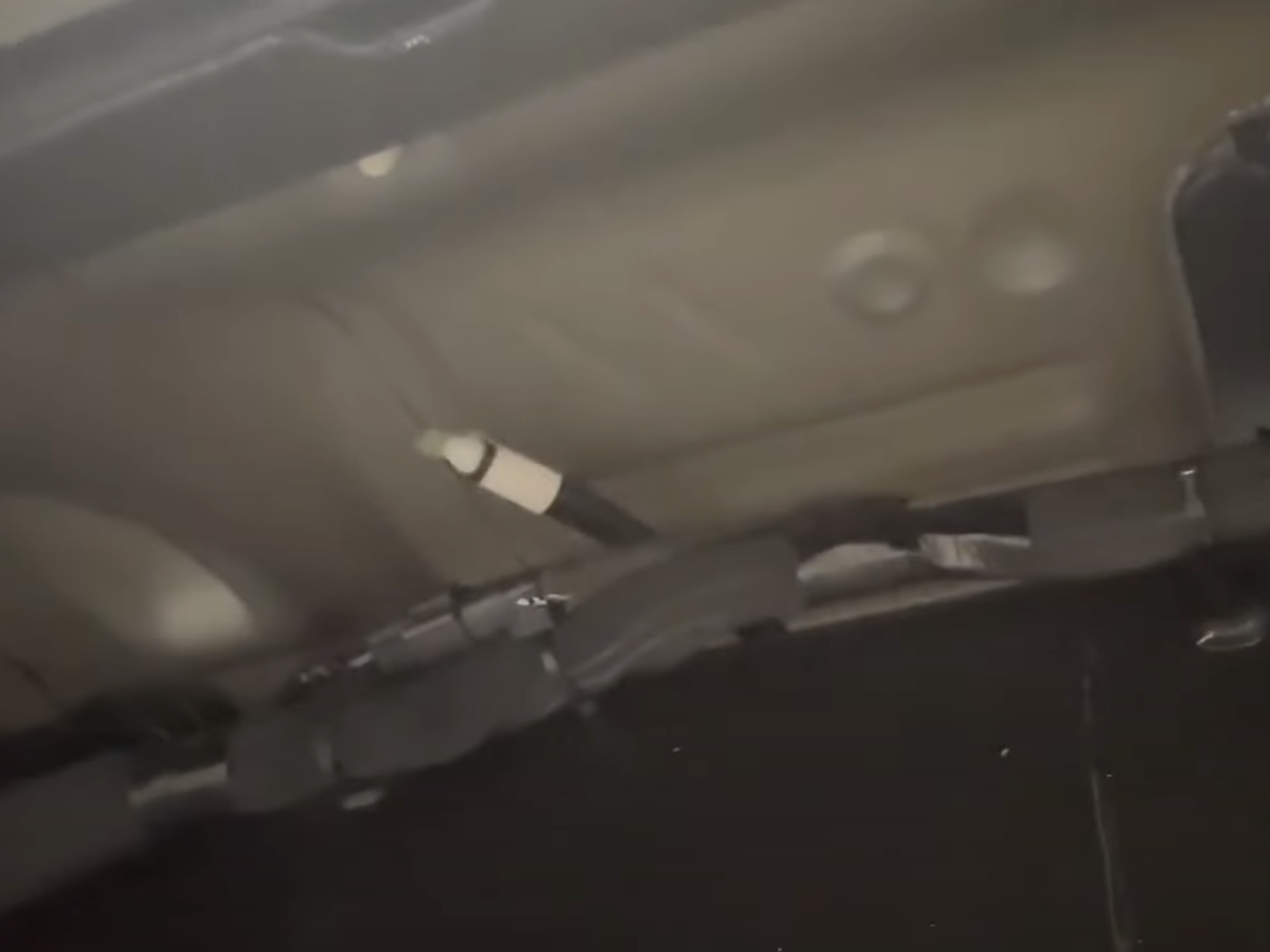
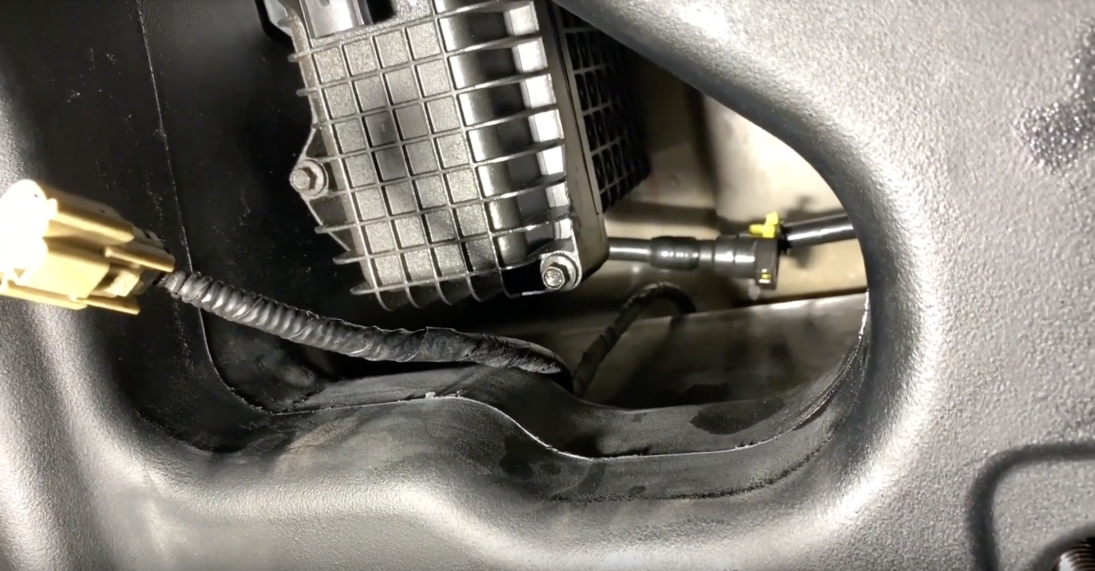
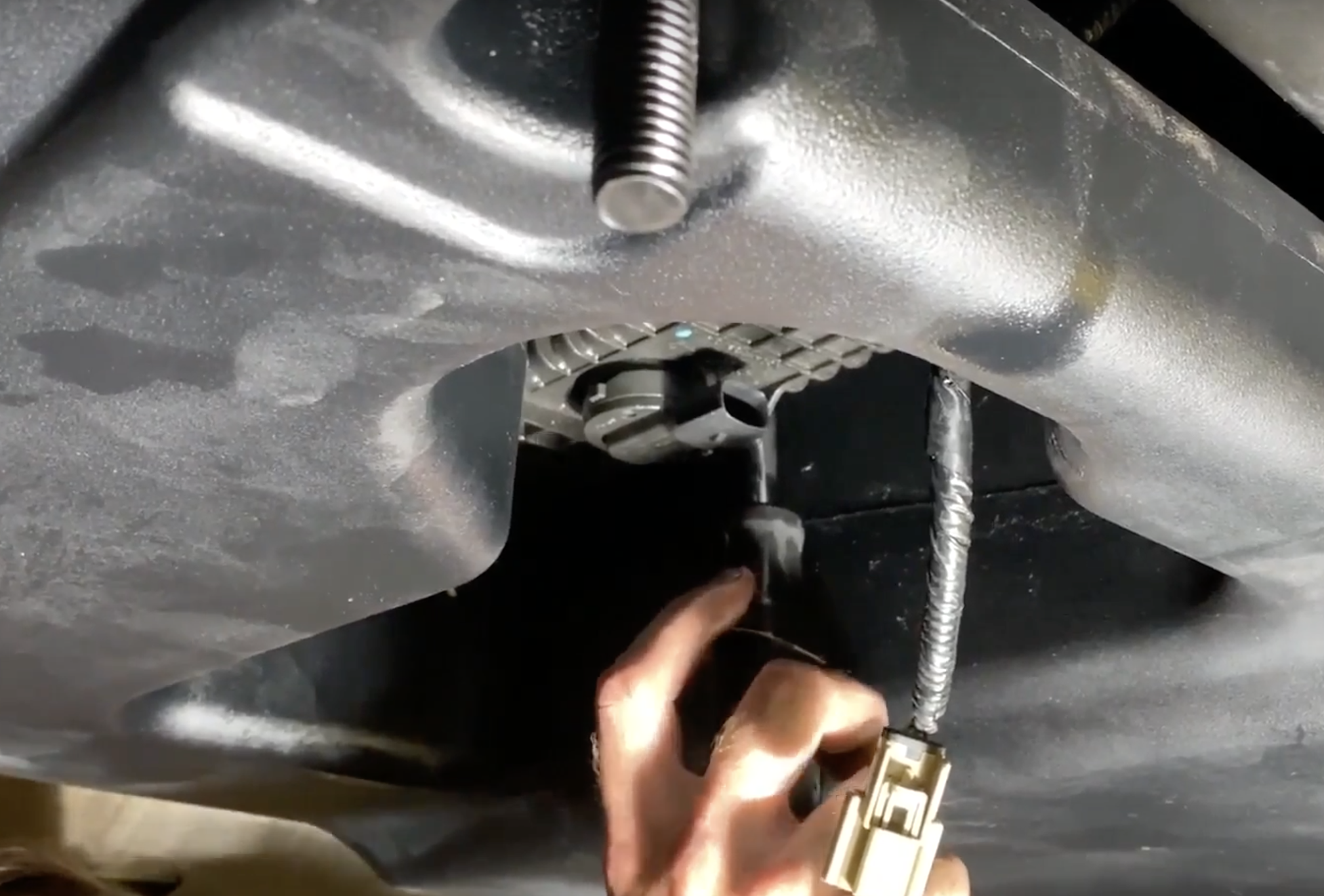
Reach over the frame rail to disconnect the electrical connection for the sending unit. Depress the tab and the connector will release.
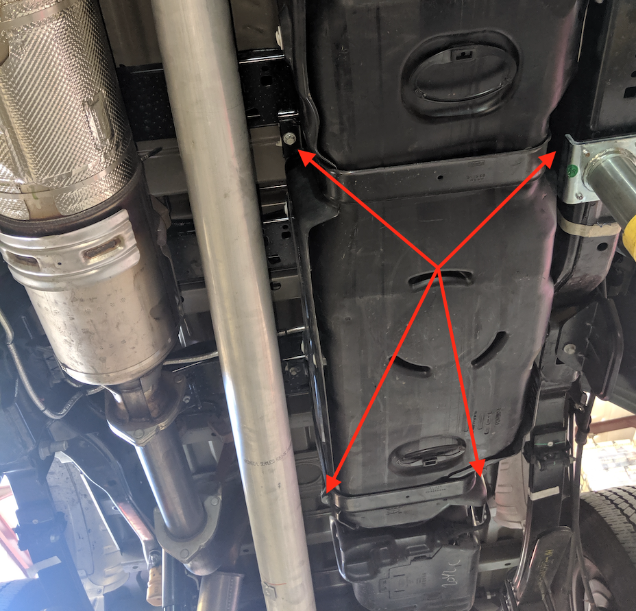
Remove the 4 bolts holding the 2 tank straps in place with a 13mm socket. Do NOT use a drill/air ratchet or you risk spinning the cage nuts.
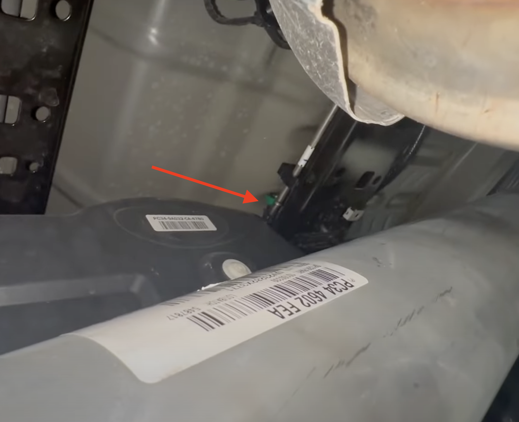
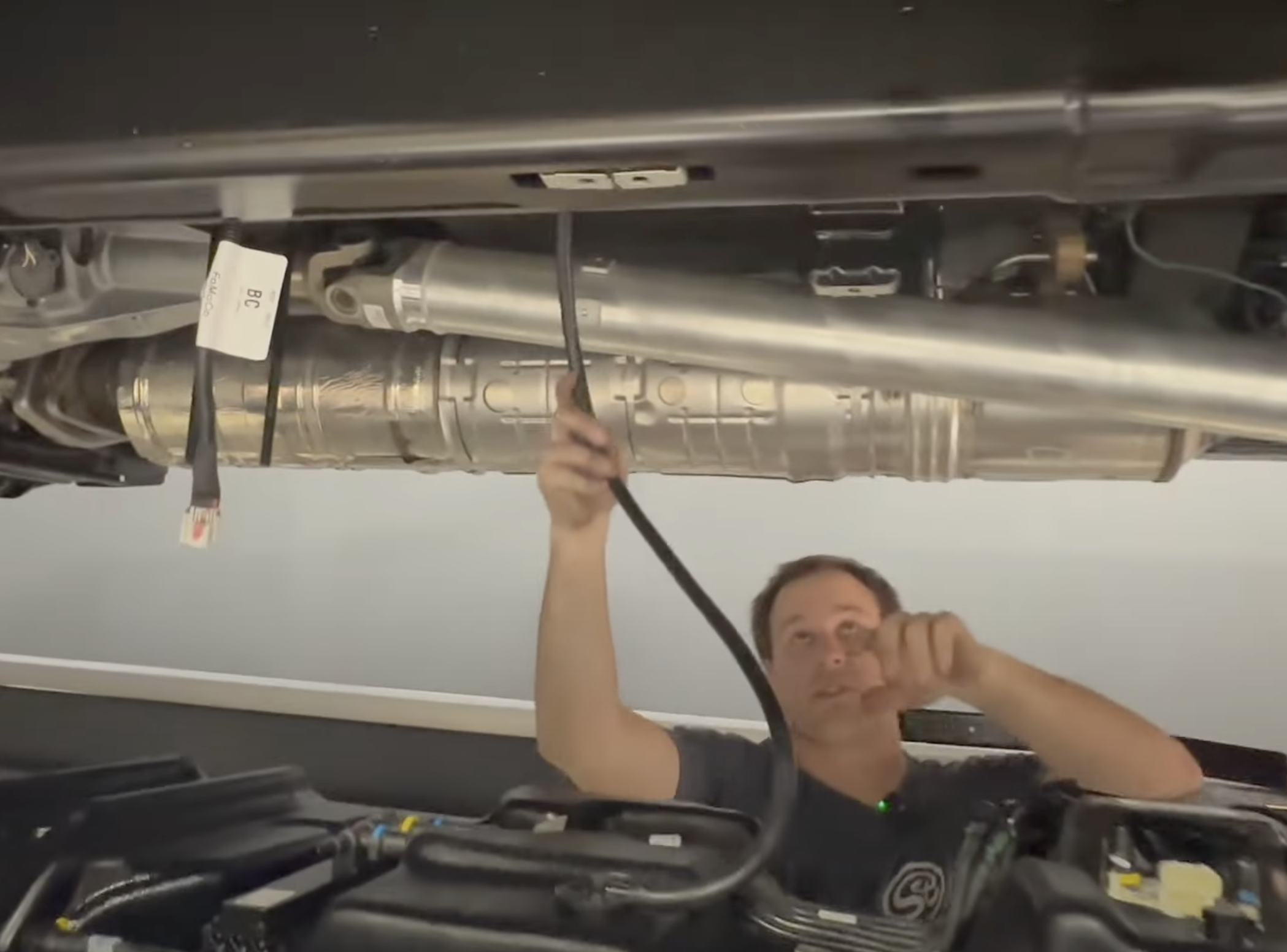
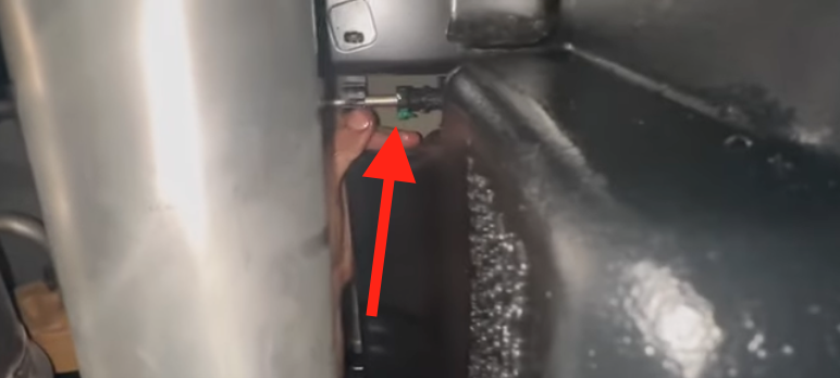
On 2023-24 Models, there is a fuel line that connects into the DPF. To remove this line, depress the button and slide out the green tab.
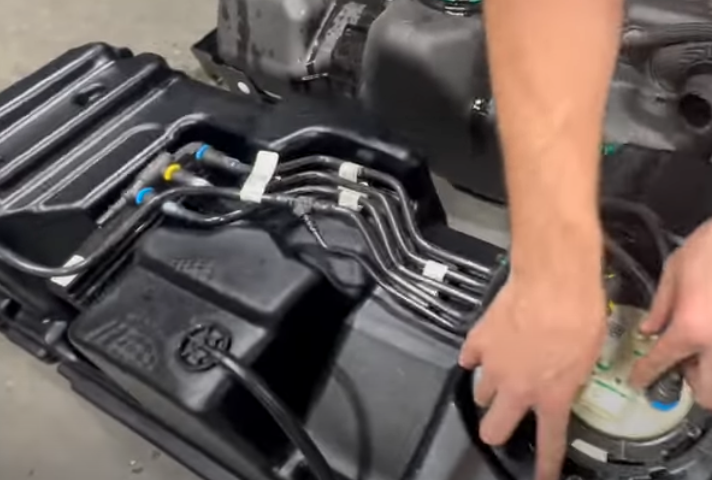
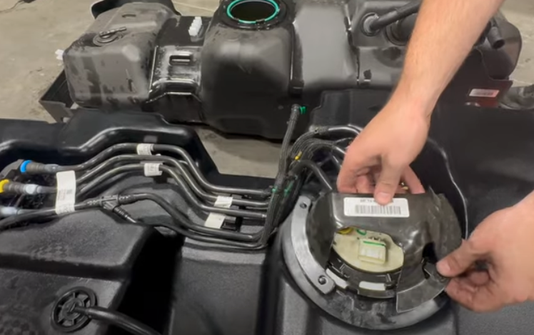
Remove the 3 nuts that hold the sending unit guard to the locking ring with a 10mm socket. It is important to remember the orientation of the sending unit guard.
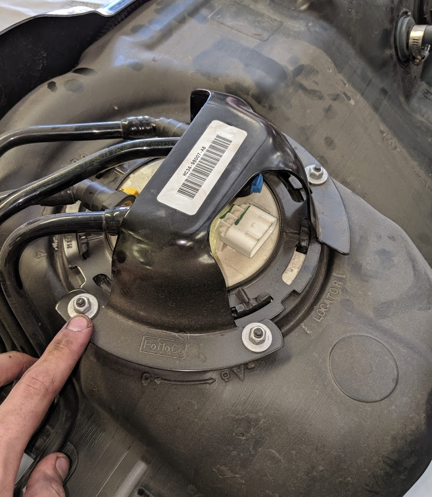
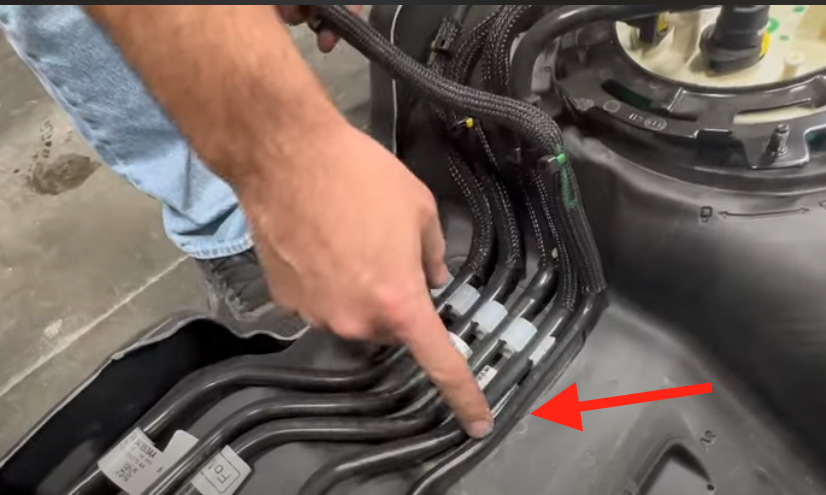
Remove the fuel lines from the hold down on the OEM tank. Simply pull upwards on the lines to pop them out. The new DPF line that is pointed out in the picture will not have a place in the bracket.
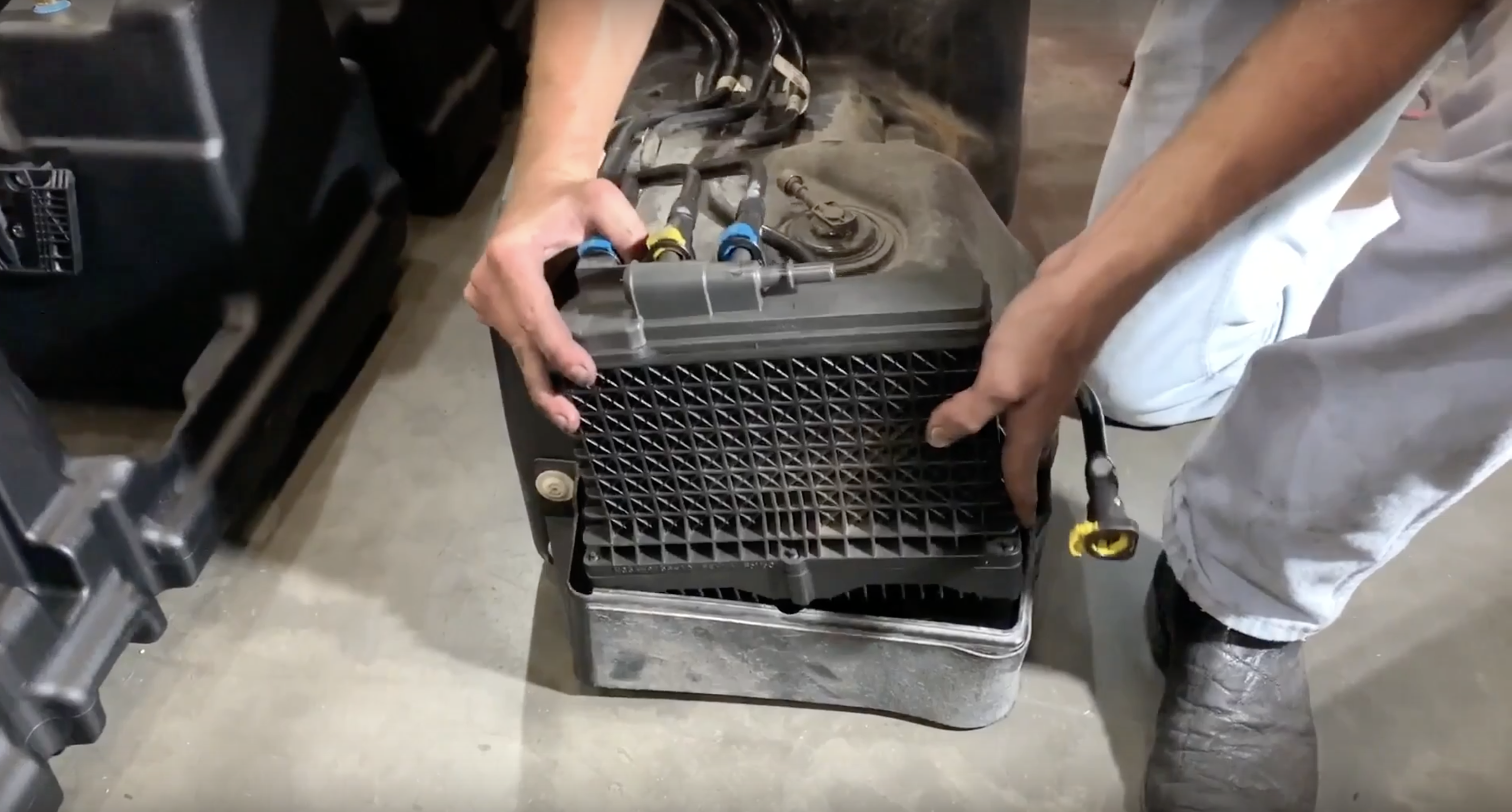
Remove the fuel water separator from its bracket. Simply pull upwards on the separator to remove it.
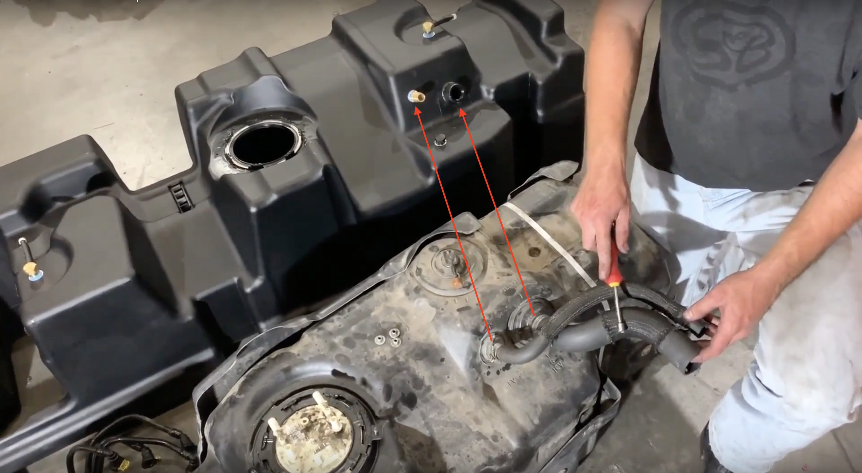
Move the fill and vent lines over to your new S&B Tank. Make sure they are installed in the same orientation as they were on the OEM tank
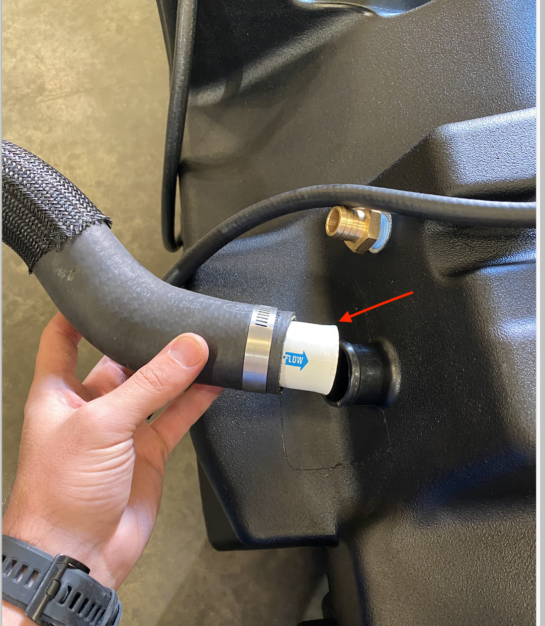
Before installing the filler hose onto the S&B Tank. Place the white check valve into the bottom of the filler hose with the blue arrow pointing into the tank.
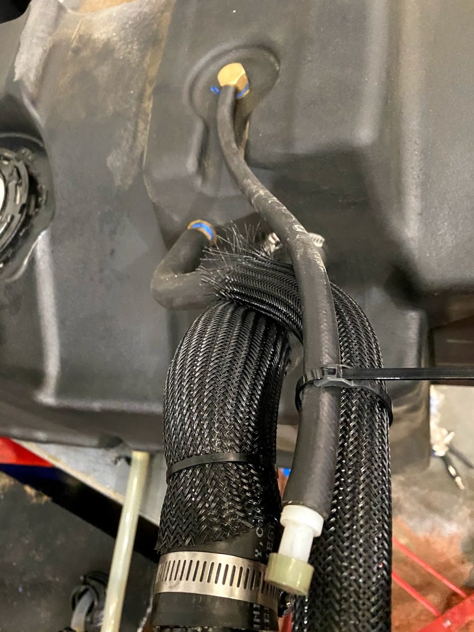
Zip tie the rear vent to the filler hose or main vent line. Make sure there are no sags in this line.
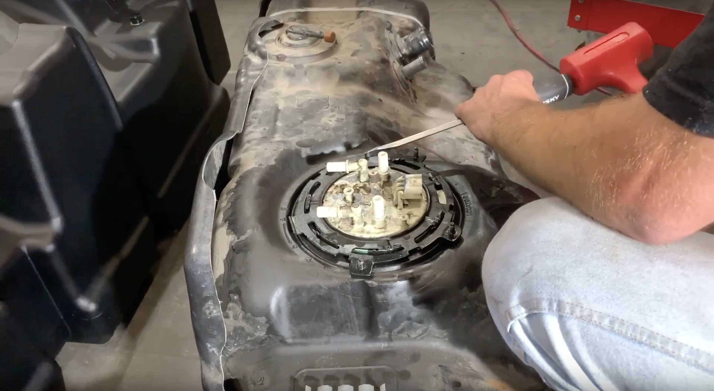
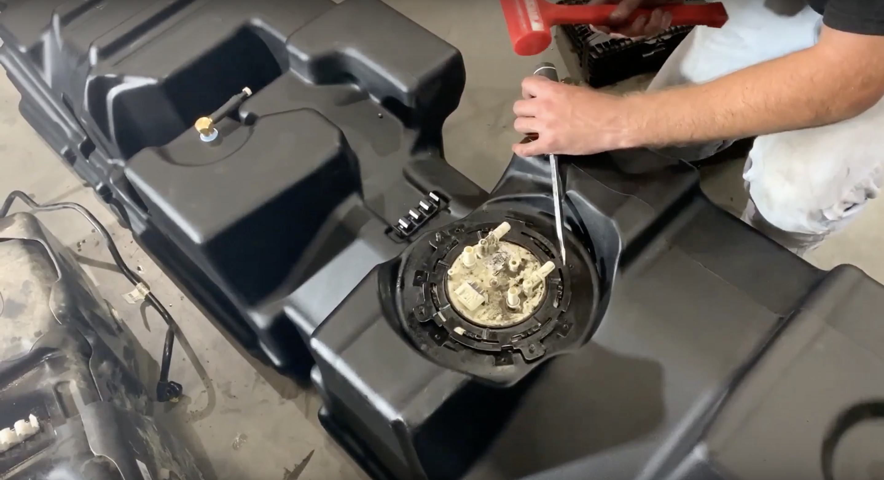
Remove the sending unit by hammering the locking ring counter clockwise.
According to the Ford TSB 17-0046. If your truck has a build date prior to 3-20-17. Replace the fuel Level Sender Resistor Card Assembly with Ford part # HC3Z-9A299-N. Watch Here
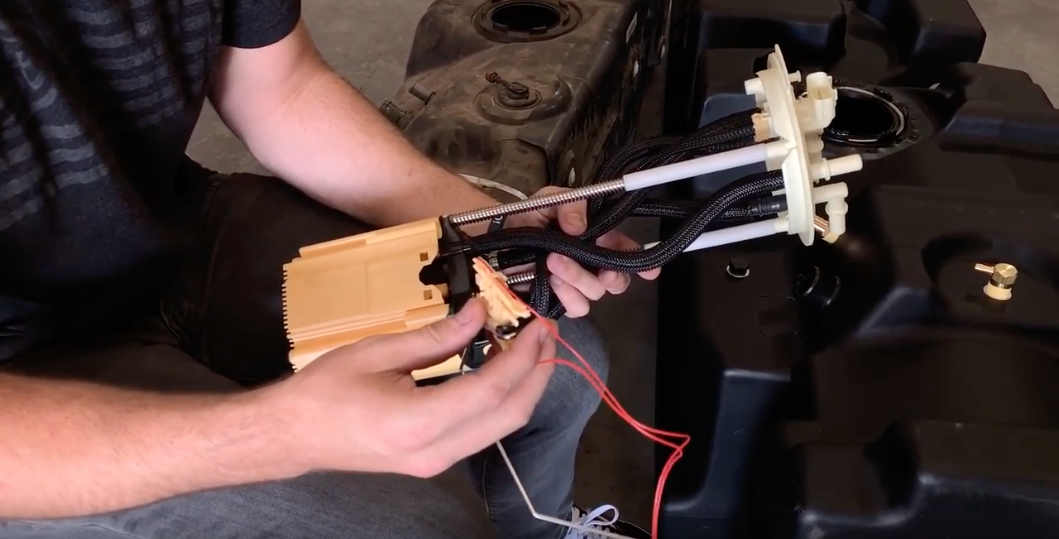
Place the black S&B o-ring in the o-ring groove and then carefully put the OEM sending unit(with OEM float attached) into the tank with the tab on the sending unit facing the arrow molded into the tank.
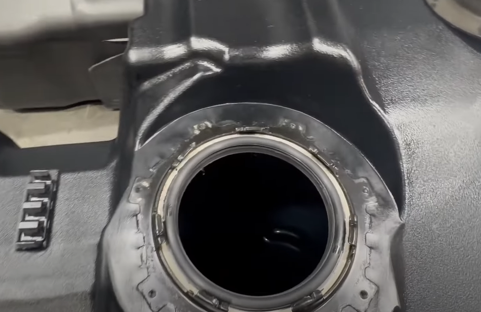
Secure the sending unit into the tank. Make sure the locking ring is oriented as it was on the OEM Tank so the sending unit guard will install without interference. Hammer the locking ring clockwise and ensure the rib on the locking ring slides into the indentation of the receiving ring on your S&B Tank.
Ensure the locking ring is fully rotated until the rib on the OEM locking ring is PAST the indentation on the S&B receiving ring. The locking ring should be very tight and not move after it's past the indentation. This insures sufficient o'ring compression.
Install the fuel water separator onto the S&B Tank. To install simply push the separator onto the bracket that is installed on the S&B Tank. Don't worry about the bolt for now, it is easier to do that once the tank is in the truck.
Reinstall the fuel lines into the fuel line holder on the S&B Tank.
Install the sending unit guard back onto the locking ring. If the guard doesn't fit over the fuel lines, your locking ring isn't oriented correctly. Do not over tighten these bolts.
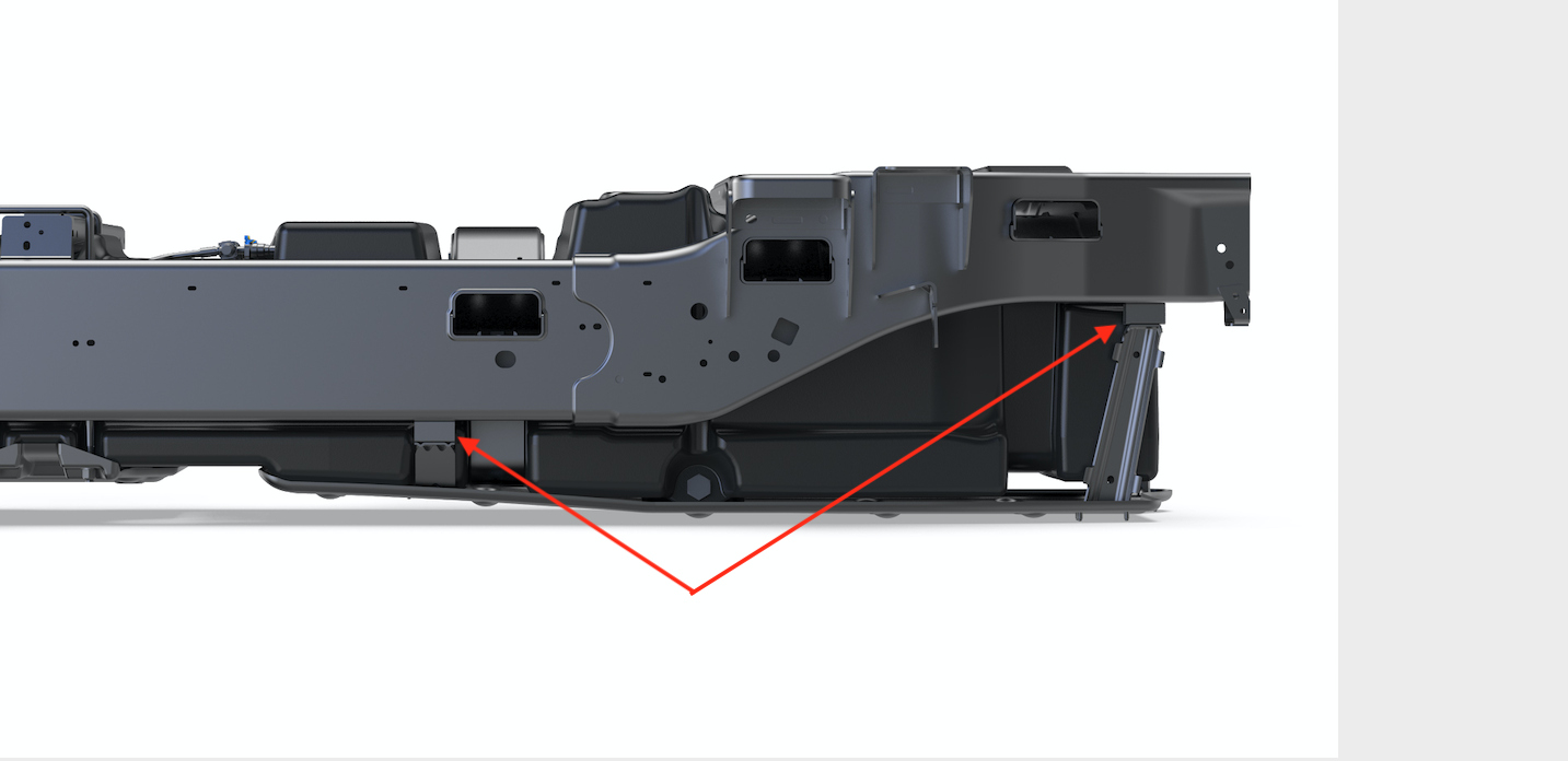
Remove the two fuel lines from the bracket on the frame. Slide the wider U Bolt up and over the crossmember. Position it between the fuel lines and the frame rail. Reinstall the fuel lines into the bracket.
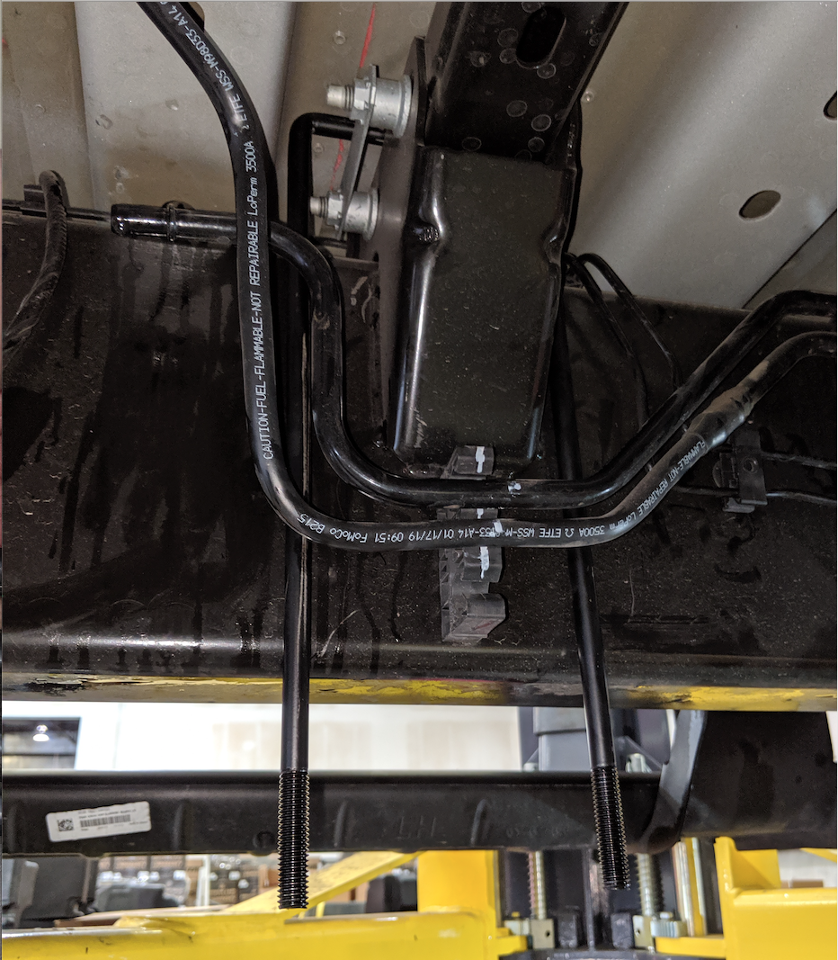
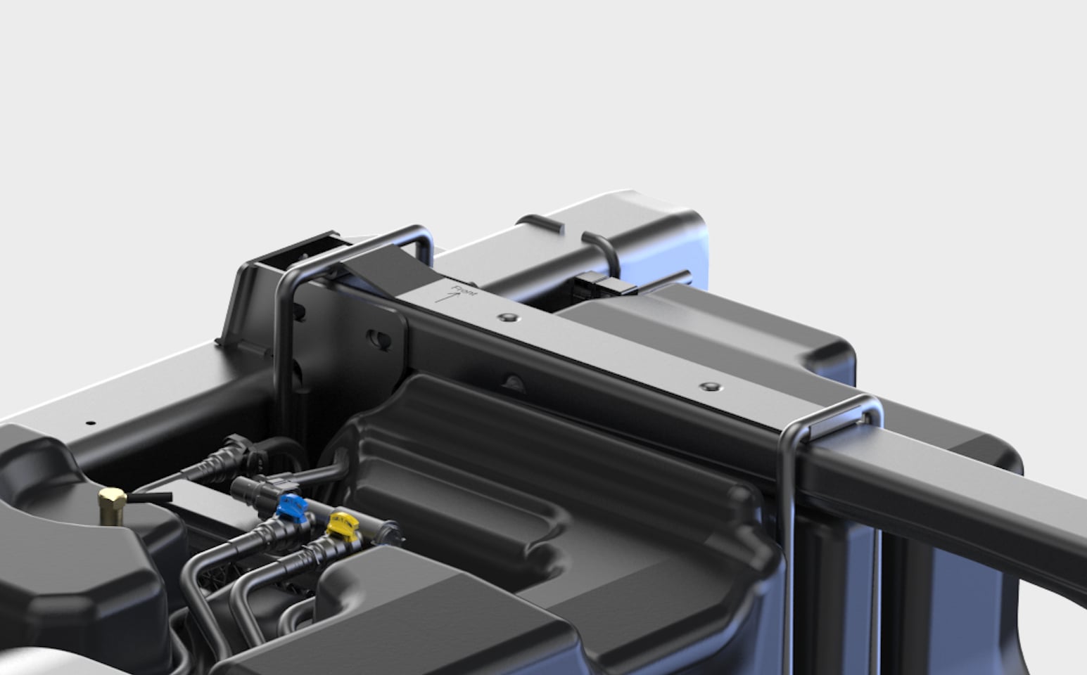
Slide the narrower U Bolt up and over the crossmember and position it against the driveshaft. Take your U Bolt positioning bracket and slide it on top of the cross member. Make sure the arrow is facing forwards. Align the holes on the bracket with the holes in the crossmember. Please proceed to step 24b and secure the bracket with the included nuts and bolts
- Tip: To keep the Ubolt in place while installing the tank, place a piece of duct tape over the Ubolt
- Important: If the u-bolts (G & F) are not positioned on the crossmember bracket (F) correctly, the tank will not be secured properly and can lead to the tank shifting
Secure the bracket in place with the included hardware.
You are now ready to raise your S&B Tank into place. It is important to guide the fill and vent lines over the frame rail while raising the tank into position. Also make sure to plug in the sending unit electrical connection while the tank is roughly 6" from being fully installed.
Route hose over crossmembers and zip tie to the filler neck
Reinstall the filler neck and vent assembly. Slide the hoses over the assembly and tighten the hose clamps(44 lb.in)

Reconnect the electrical connection for the sending unit.
Connect all of the fuel water separator connections. To reconnect the yellow clip fuel line connector, slide it back onto the frame mounted fuel line and press the locking tab back into place. For the blue fuel line connector, slide it back onto the top of the water separator and slide the locking ring back to the locked position. At this point you can also connect the electrical connector at the bottom of the separator.
Reinstall the Torx water separator screw. If the screw will not easily thread in, your water separator isn't fully seated on the bracket. Wiggle it gently while looking through the bolt hole to see when it fully seats.
- Torx 30
Reconnect the DPF line.
With the tank fully raised, install the tank straps and bolts(30 lb.ft (40 Nm). All 4 strap bolts are 13mm. We like to install the longer of the 4 bolts in the middle strap driver side bolt position.
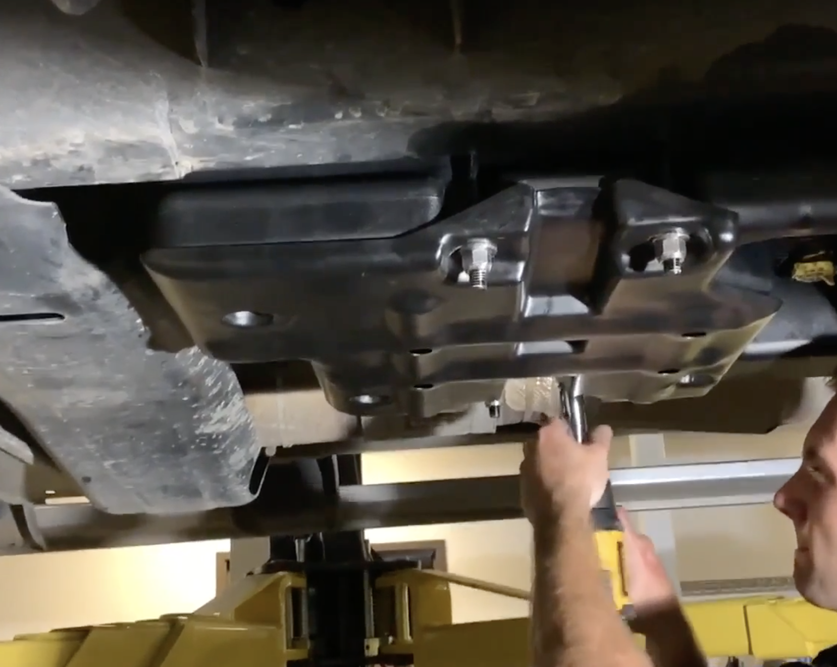
Install the front S&B Skid Plate Support. Guide the U-bolts through the holes on the skid plate and use a washer and nylon lock nut on each U-bolt. Make sure to start these lock nuts by hand before tightening down. Use a hand ratchet to torque these in a diamond pattern to ensure the skid plate contacts the tank evenly. THIS FRONT SUPPORT SKID PLATE MUST BE INSTALLED
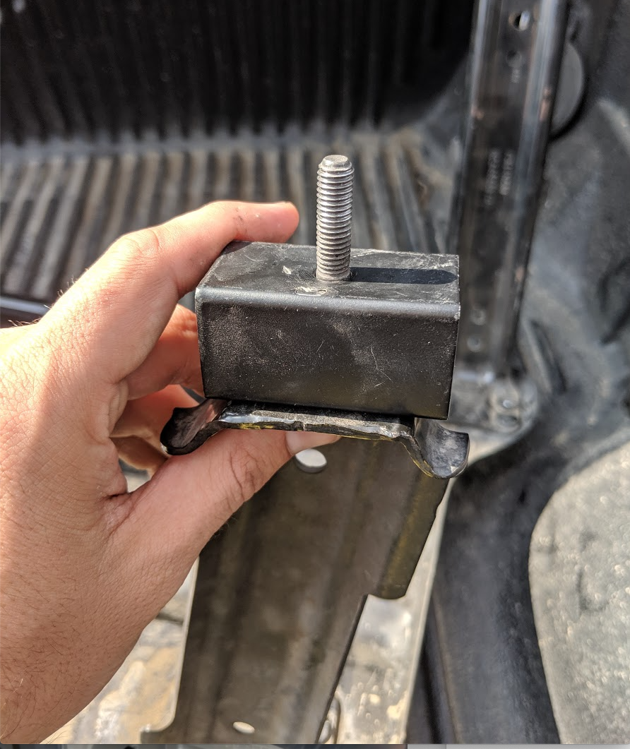
Install the OEM Skid Plate if your truck was equipped with one. Use the S&B provided 1.75" skid plate spacers and new hardware. Ensure the skid plate spacers are lined up with their corresponding position. The driver side front corner gets a spacer with 2 lined up holes, the passenger side rear spacer has 2 offset holes, and the other 2 positions only have 1 hole.
The 1.75" spacers go in between the skid plate strap and crossmember or frame on the truck. Use the provided S&B bolts.
Make sure the u-bolts are positioned correctly on the crossmember bracket.

This final checklist is very important.
#1 Make sure all bolts and nuts are safely fastened and torqued.
#2 Ensure there is proper driveshaft clearance.
#3 If you reinstalled the OEM skid plate, make sure the edges of the skid plate can't rub the tank. If they are, you'll need to bend the edges of the skid plate out and/or add washers to the skid plate spacer.
#4 Double check fuel line connections, the electrical connection as well as the vent and fill lines.
#5 Lastly, fill the tank full and check for any leaks.
If you have any questions, call or text us at 909.675.1313